


From Basic Flows to Parallel Actions and Decision Modeling
Introduction
Activity Diagrams are a cornerstone of UML modeling, providing a visual representation of workflows, business processes, and system behaviors. Whether you’re designing software architecture, documenting business rules, or planning user interactions, mastering Activity Diagrams in Visual Paradigm empowers you to communicate complex processes with clarity and precision.

This comprehensive guide walks you through a structured lab exercise designed to build proficiency in creating, modifying, and enhancing Activity Diagrams using Visual Paradigm for UML. You’ll learn to replicate lecture examples, model parallel actions with Fork/Join nodes, incorporate decision logic with guards and timed events, and apply professional formatting techniques. By the end of this guide, you’ll have both the conceptual understanding and practical skills to create publication-ready Activity Diagrams for academic, professional, or personal projects.
Key Concepts & Foundations
What is an Activity Diagram?
-
A behavioral UML diagram that models the flow of control or object flow from activity to activity
-
Represents workflows, business processes, or operational procedures
-
Supports parallel processing, decision points, object states, and timed events
Core Visual Paradigm Elements
| Element | Purpose | Key Tip |
|---|---|---|
| Activity | Container for related actions | Resize early to accommodate all child nodes |
| Action | Atomic step in a workflow | Use descriptive, verb-noun names |
| Object Node | Represents data/objects flowing between actions | Define Type and InStates for clarity |
| Activity Parameter | Input/output boundary for the Activity | Distinguish from Object nodes—parameters are external |
| Object Flow | Shows objects/data moving between nodes | Use for object-carrying connections |
| Control Flow | Shows execution order without object transfer | Use for pure control logic |
| Fork/Join Nodes | Model parallel/concurrent execution | Horizontal orientation often improves readability |
| Decision/Merge Nodes | Model conditional branching and convergence | Always label guards for clarity |
| Accept Time Event | Models timed delays or scheduled triggers | Found in stacked Action icons |
Pro Tips for Visual Paradigm
-
Colors & Fonts: Use the “Presentation Options” menu to maintain consistent styling across diagrams
-
Icon Discovery: Many icons (Fork, Join, Decision, Time Event) are stacked—click and hold to reveal options
-
Exporting: Use PNG or SVG for presentations; PDF for documentation; always check resolution settings
-
Specification Panels: Right-click → Open Specification to configure Types, States, and Guards
-
Alignment: Use Visual Paradigm’s alignment guides to keep nodes professionally spaced
Preparation Phase
General Preparation
-
Open the course “Help” page on “Visual Paradigm – Tips”
-
Read the section on “Colors, Fonts, etc…” to establish visual consistency
-
Read “Finding Icons” to efficiently locate stacked diagram elements
-
Review “Exporting Diagrams” to ensure your final output meets submission requirements
Specific Preparation: Activity Diagrams
-
Read the “Activity Diagrams” section in Visual Paradigm documentation
-
Familiarize yourself with UML 2.5 Activity Diagram notation
-
Review lecture examples to understand expected structure and semantics
Part 1: Replicating the “Do Laundry” Example
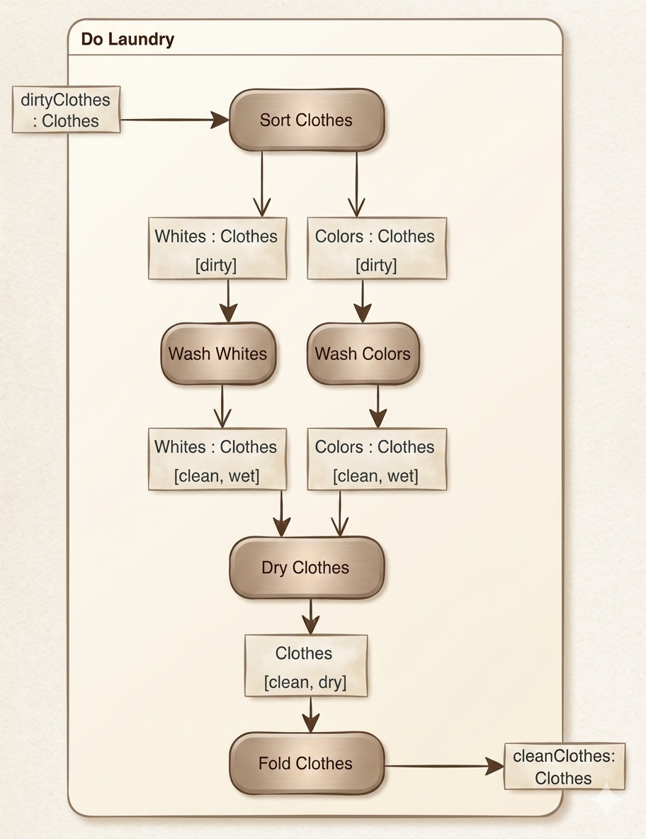
Step-by-Step Implementation
-
Create the Activity Container
-
Add a new Activity (not Action) named
"Do Laundry" -
Resize it generously to accommodate all subsequent nodes
-
-
Add Initial Action & Parameter
-
Add Action:
"Sort Clothes" -
Add Activity Parameter (not Object node):
"dirtyClothes"as input -
Right-click
"dirtyClothes"→ Open Specification → General tab → Set Type = “Clothes” → OK
-
-
Connect Parameter to Action
-
⚠️ Try adding a Control Flow from
"dirtyClothes"to"Sort Clothes" -
❓ What happens and why?
Control Flows cannot carry objects. Since
"dirtyClothes"is a typed parameter (Clothes), you must use an Object Flow to preserve type information and object semantics.
-
-
Add Object Nodes with States
-
Add Object Flow from
"dirtyClothes"to"Sort Clothes" -
Add Object Node:
"Whites" -
Right-click
"Whites"→ Open Specification:-
General tab: Type = “Clothes”
-
InStates tab: Add state
"dirty"→ Select it → OK
-
-
Right-click
"Whites"→ Presentation Options → Show InStates → Yes -
Adjust node size to display state label clearly
-
Repeat for
"Colors"Object Node with identical configuration
-
-
Connect Sorting to Washing
-
Add Object Flows:
"Sort Clothes"→"Whites"and"Sort Clothes"→"Colors" -
Add Actions:
"Wash Whites"and"Wash Colors" -
Add Object Flows:
"Whites"→"Wash Whites"and"Colors"→"Wash Colors"
-
-
⚠️ Critical Thinking Question
❓ Which Action happens first, “Wash Whites” or “Wash Colors”, or do they happen at the same time?

Answer: Without explicit Fork/Join nodes, UML semantics allow either order or parallel execution. The diagram implies potential concurrency, but does not enforce it. For guaranteed parallelism, use Fork nodes (covered in Part 2).
-
Complete the Washing Cycle
-
Add Object Nodes for output:
"Whites [clean, wet]"and"Colors [clean, wet]" -
Add Object Flows from washing actions to these nodes
-
Add Action:
"Dry Clothes"(resize to align with"Sort Clothes") -
Add Object Flows from both
[clean, wet]nodes to"Dry Clothes"
-
-
⚠️ Synchronization Question
❓ When can/does the “Dry Clothes” Action begin?
Answer: “Dry Clothes” can begin only after both “Wash Whites” and “Wash Colors” complete and produce their
[clean, wet]outputs. Without a Join node, this dependency is implicit but not enforced—another reason to use explicit synchronization (Part 2). -
Finalize Diagram
-
Add output Activity Parameter if needed (e.g.,
"cleanClothes") -
Ensure all flows are properly typed and labeled
-
Verify visual alignment and readability
-
Part 2: Modeling Parallel Actions with Fork/Join
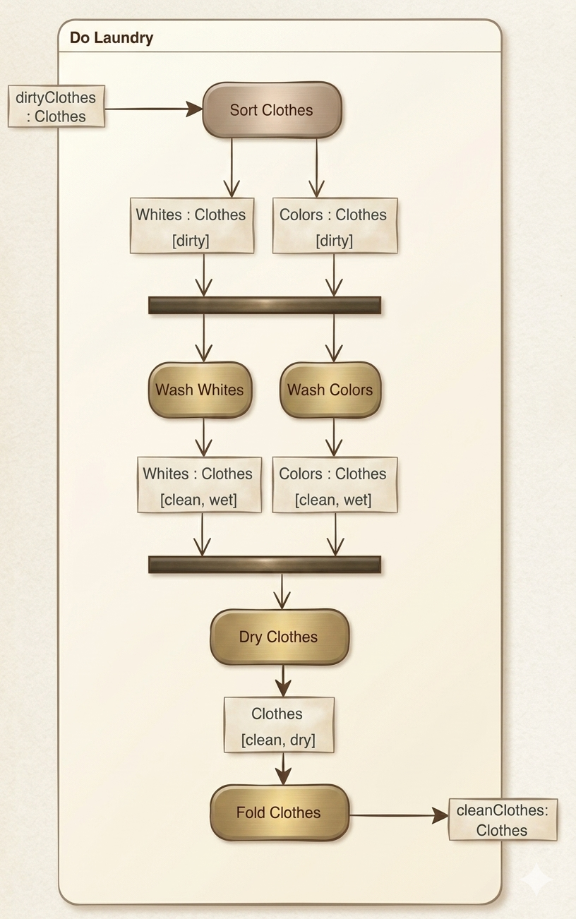
Enhancing Concurrency
-
Prepare Canvas
-
Increase vertical size of
"Do Laundry"Activity -
Move input/output parameters if needed to avoid overlap
-
Select all nodes below
"Whites [dirty]"/"Colors [dirty]"and move lower for spacing
-
-
Insert Fork Node for Parallelism
-
Delete existing Object Flows into
"Wash Whites"and"Wash Colors" -
Locate Fork Node icon (stacked with Decision/Join—expand stack to select)
-
Place Fork Node below the two
[dirty]Object Nodes -
Set orientation to horizontal; adjust width to span both input flows
-
Add Object Flows:
"Whites [dirty]"→ Fork and"Colors [dirty]"→ Fork -
Add Control Flows: Fork →
"Wash Whites"and Fork →"Wash Colors"
-
-
Insert Join Node for Synchronization
-
Delete Object Flows into
"Dry Clothes" -
Add Join Node below
"Whites [clean, wet]"and"Colors [clean, wet]" -
Set horizontal orientation; adjust size
-
Add Object Flows from both
[clean, wet]nodes → Join -
Add Control Flow: Join →
"Dry Clothes"
-
-
⚠️ Concurrency Verification
❓ Now which Action happens first, “Wash Whites” or “Wash Colors”, or do they happen at the same time?
Answer: With the Fork node explicitly splitting control, “Wash Whites” and “Wash Colors” execute in parallel. The Join node ensures “Dry Clothes” waits for both to complete.
-
⚠️ Real-World Modeling Reflection
❓ In the real world, is it always possible to wash whites and colors at the same time?
Answer: Not necessarily. Physical constraints (one washer, limited resources) may prevent true parallelism. This highlights a key modeling principle: diagrams represent intended logic, not physical reality. To model resource constraints, add guards, resource pools, or sequence constraints.
Part 3: Modeling Decisions & Timed Events
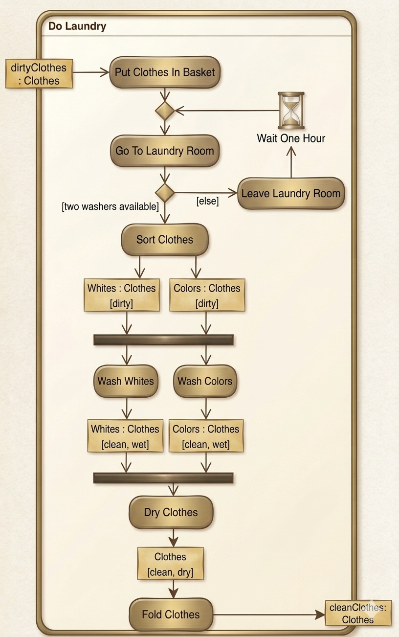
Adding Conditional Logic and Time-Based Behavior
-
Expand Activity Canvas
-
Increase both vertical and horizontal size of
"Do Laundry"
-
-
Pre-Sort Preparation Phase
-
Delete Object Flow into
"Sort Clothes" -
Add Action:
"Put Clothes In Basket"above"Sort Clothes" -
Add Object Flow:
"dirtyClothes"parameter →"Put Clothes In Basket" -
Add Action:
"Go To Laundry Room"below"Put Clothes In Basket"
-
-
Decision Node with Guards
-
Add Decision Node below
"Go To Laundry Room"(expand stacked icons) -
Add Control Flow:
"Go To Laundry Room"→ Decision -
Add Control Flow: Decision →
"Sort Clothes"-
Right-click flow → Open Specification → Guard:
"two washers available"
-
-
Add Action:
"Leave Laundry Room"to right of Decision -
Add Control Flow: Decision →
"Wait One Hour"-
Set Guard:
"else"
-
-
-
Timed Event Handling
-
Add Accept Time Event Action:
"Wait One Hour"above"Leave Laundry Room"(stacked Action icon) -
Add Control Flow:
"Leave Laundry Room"→"Wait One Hour"
-
-
⚠️ Flow Design Pitfall
❓ You might be inclined to add one Control Flow from “Put Clothes In Basket” to “Go To Laundry Room” and another from “Wait One Hour” to “Go To Laundry Room”. Why would this be inappropriate?
Answer: This creates a cycle without explicit convergence, potentially implying infinite looping or ambiguous re-entry. UML requires clear merge points for converging paths to maintain deterministic semantics.
-
⚠️ Solution Strategy
❓ How can we resolve this problem?
Answer: Insert a Merge Node between
"Put Clothes In Basket"and"Go To Laundry Room". Route both the initial path and the post-wait path into the Merge, then flow from Merge →"Go To Laundry Room". This explicitly models convergence. -
Finalize Decision Flow
-
Add Merge Node between
"Put Clothes In Basket"and"Go To Laundry Room" -
Add Control Flows:
-
"Put Clothes In Basket"→ Merge -
"Wait One Hour"→ Merge -
Merge →
"Go To Laundry Room"
-
-
Verify all guards, states, and types are correctly configured
-
Tips, Tricks & Best Practices
🎨 Visual Clarity
-
Consistent Styling: Use Presentation Options to standardize fonts, colors, and line weights
-
Strategic Spacing: Leave 20-30px between nodes; use alignment guides
-
Label Everything: Guards, states, types, and parameters should be visible and legible
-
Layering: Use Activity containers to group related actions hierarchically
⚙️ Technical Efficiency
-
Keyboard Shortcuts: Learn VP shortcuts for node creation, duplication, and alignment
-
Template Saving: Save a styled Activity Diagram template for future projects
-
Version Control: Export incremental versions (v1, v2, final) to track evolution
-
Validation: Use Visual Paradigm’s built-in UML validator to catch semantic errors
🧠 Modeling Wisdom
-
Start Simple: Build sequential flows first, then add concurrency/decisions
-
Test Semantics: Ask “What must happen before X?” for every node
-
Document Assumptions: Use notes or comments for real-world constraints not shown in diagram
-
Iterate: Refine diagrams based on stakeholder feedback—clarity trumps completeness
🚫 Common Pitfalls to Avoid
| Pitfall | Consequence | Solution |
|---|---|---|
| Using Control Flow for object transfer | Loss of type information; semantic errors | Use Object Flow for typed data |
| Forgetting to show InStates | Ambiguous object conditions | Always configure and display relevant states |
| Overusing parallelism | Unrealistic models; resource conflicts | Model constraints with guards or resource pools |
| Unlabeled guards | Unclear decision logic | Always specify guard conditions explicitly |
| Missing Merge nodes | Ambiguous path convergence | Use Merge for all converging control flows |
Conclusion
Mastering Activity Diagrams in Visual Paradigm is more than learning a tool—it’s developing a disciplined approach to modeling dynamic behavior. This lab exercise has equipped you with foundational skills: creating typed object flows, modeling concurrency with Fork/Join, implementing conditional logic with guarded decisions, and handling time-based events.
Remember that effective diagrams balance precision with readability. Every node, flow, and label should serve a communicative purpose. As you advance, challenge yourself to model increasingly complex workflows while maintaining clarity. Use Visual Paradigm’s AI-powered features (like Use Case to Activity Diagram conversion) to accelerate prototyping, but always review and refine generated diagrams to ensure semantic accuracy.
Whether you’re documenting a laundry workflow or designing enterprise software processes, the principles you’ve practiced here—explicit typing, clear synchronization, guarded decisions, and visual consistency—will serve as your foundation for professional-grade UML modeling. Keep experimenting, keep refining, and let your diagrams tell the story of your system’s behavior with confidence.
References
-
Visual Paradigm User Guide: Drawing Activity Diagrams: Step-by-step instructions for manually creating Activity Diagrams using Visual Paradigm’s drag-and-drop interface and resource catalog.
-
Use Case to Activity Diagram Feature Page: Official overview of Visual Paradigm’s AI-powered tool that converts textual use cases into UML Activity Diagrams instantly.
-
What is an Activity Diagram? – Visual Paradigm Guide: Comprehensive introduction to Activity Diagrams, including notation, use cases, and practical examples.
-
Visual Paradigm Online Tour: Overview of Visual Paradigm Online’s web-based diagramming capabilities, including export options and collaboration features.
-
How to Draw Activity Diagrams in UML – Tutorial: Beginner-friendly tutorial covering fundamental concepts and step-by-step diagram creation.
-
Activity Diagram Tutorial (Legacy Documentation): Archived tutorial providing foundational knowledge on Activity Diagram modeling techniques.
-
Visual Paradigm Desktop AI Activity Diagram Generation Release Notes: Technical details on the AI-powered diagram generation feature for desktop users.
-
YouTube: Activity Diagram Tutorial: Video walkthrough demonstrating Activity Diagram creation and best practices.
-
Import AI Activity Diagrams into Visual Paradigm Desktop: Guide for importing AI-generated diagrams into desktop projects.
-
Blog: Generate Activity Diagrams from Use Cases Instantly: Announcement and use cases for the AI-powered Use Case to Activity Diagram feature.
-
User Story to Activity Diagram Tutorial: Instructions for synchronizing agile user stories with Activity Diagrams.
-
Beginner’s Guide to Activity Diagrams with Visual Paradigm Online: Entry-level guide for new users of Visual Paradigm Online.
-
YouTube: Advanced Activity Diagram Techniques: Video covering advanced notation, swimlanes, and complex workflow modeling.
-
James Madison University: Visual Paradigm Activity Diagram Lab: Academic lab exercise for practicing Activity Diagram creation.
-
SysML Activity Diagram Guide: Specialized guide for using Activity Diagrams within SysML for systems engineering.
-
AI-Powered Use Case to Activity Diagram Generator: Third-party review and tutorial on leveraging Visual Paradigm’s AI tools for UML modeling.