


In the complex architecture of modern software systems, the flow of information determines stability and performance. While developers often focus on code implementation, the blueprint of that code—the design diagrams—reveals the true logic of interaction. Among these, communication diagrams provide a unique perspective on how objects or components relate to one another. However, a specific element often causes confusion: the asynchronous message. 🤔
Understanding these messages is critical for anyone designing scalable systems. It moves beyond simple request-response patterns into the realm of event-driven behavior. This guide explores the mechanics, visual representation, and strategic implications of asynchronous messaging within communication diagrams. We will dissect how these flows differ from synchronous ones and why they matter for system reliability.
📐 What Are Communication Diagrams?
Before diving into message types, we must establish the canvas. A communication diagram (formerly known as a collaboration diagram in UML 1.x) is a type of interaction diagram. Its primary purpose is to show the interactions between objects or parts in terms of sequenced messages. Unlike sequence diagrams, which emphasize time, communication diagrams emphasize the structural organization of the participants. 🏗️
Key characteristics include:
- Structural View: Objects are arranged spatially to reflect relationships, not necessarily chronological order.
- Message Flow: Arrows connect objects, indicating the direction of data transfer.
- Sequence Numbers: Messages are numbered (1, 1.1, 1.2) to show the order of execution.
When you draw a line between two components, you are defining a contract. This contract dictates how one part of the system requests work from another. The nature of that request—synchronous or asynchronous—changes the entire lifecycle of the operation. 🔄
⚡ Synchronous vs. Asynchronous: The Core Distinction
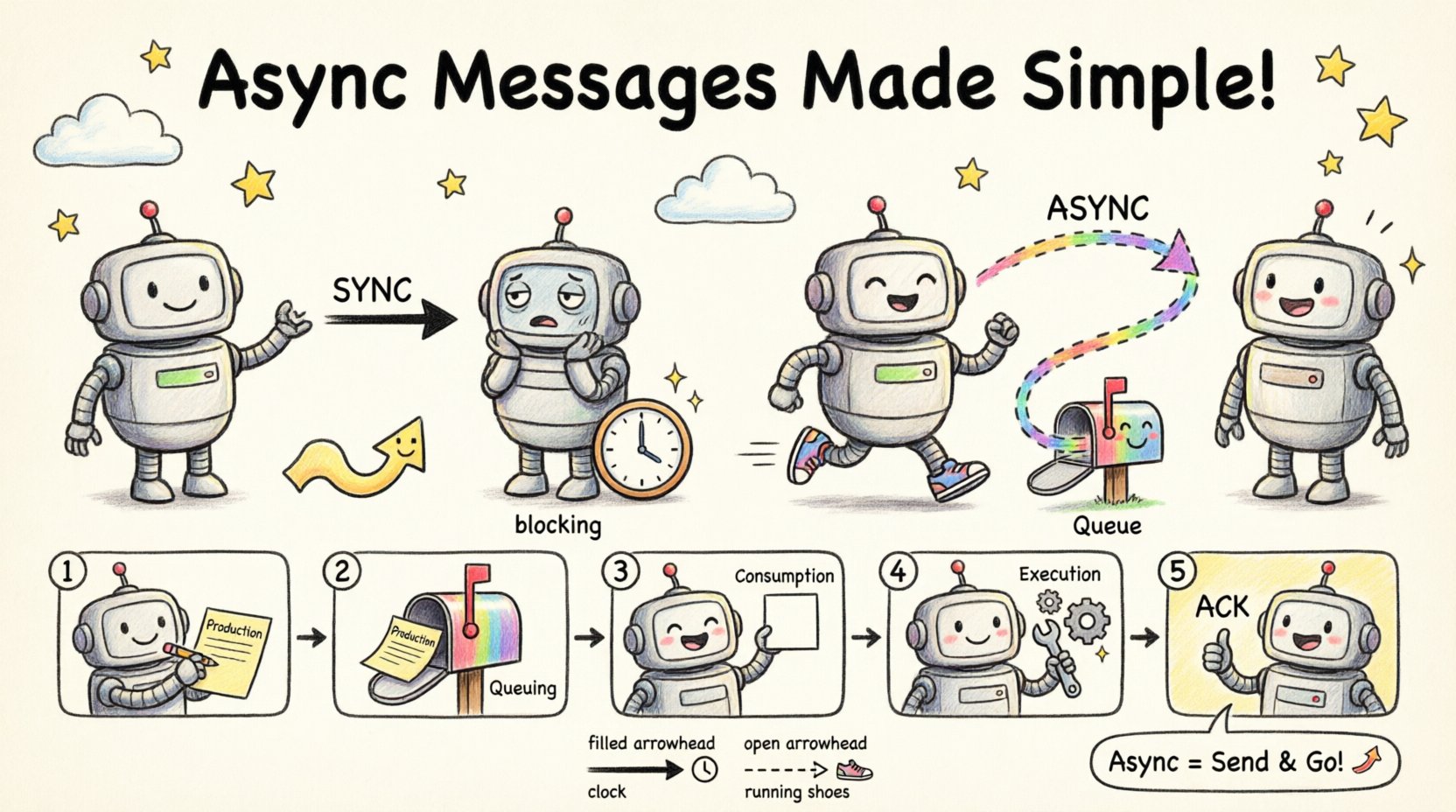
The fundamental difference lies in the caller’s behavior after sending the message. In a synchronous call, the sender waits for a response before proceeding. It is a blocking operation. In contrast, an asynchronous message is sent without an immediate expectation of a return value. The sender continues its execution immediately. 🏃♂️
This distinction impacts resource management, latency, and error handling. Here is a breakdown of the operational differences:
🛑 Synchronous Behavior
- Blocking: The thread or process halts until the recipient responds.
- Direct Dependency: The sender is tightly coupled to the recipient’s availability.
- Immediate Feedback: Errors are caught instantly if the recipient fails.
- Use Case: Critical data retrieval where the next step depends on the result.
🚀 Asynchronous Behavior
- Non-Blocking: The sender does not wait for the response.
- Decoupling: The sender and recipient can operate on different timelines.
- Deferred Feedback: Responses may arrive later via callbacks, events, or separate queries.
- Use Case: Background processing, logging, notifications, or heavy computations.
Visualizing this in a diagram requires specific notation to distinguish the two types clearly. Misinterpreting an arrow can lead to architectural flaws in production. 📉
🎨 Visual Notation for Asynchronous Messages
Standardization is key in technical documentation. When representing asynchronous messages in a communication diagram, specific arrow styles and labels are used to convey the non-blocking nature. This ensures that any engineer reading the diagram understands the flow logic without needing to read the source code. 🛠️
Arrow Styles
- Solid Arrow with Filled Arrowhead: Typically represents a synchronous call. The line is continuous, implying a direct connection.
- Dashed Arrow with Open Arrowhead: The standard convention for an asynchronous message. The dashed line signifies that the path is not a direct, immediate return trip.
Labeling Conventions
The text on the arrow provides context. For asynchronous flows, labels often include:
- Action Names: “sendNotification”, “updateCache”, “logEvent”.
- Keywords: Words like “async”, “fire-and-forget”, or “event”.
- Return Indicators: If a return is expected later, it is often shown on a separate return arrow or noted as a callback.
| Visual Element | Synchronous Message | Asynchronous Message |
|---|---|---|
| Line Type | Solid Line | Dashed Line |
| Arrowhead | Filled (Black) | Open (Hollow) |
| Timing | Immediate | Deferred |
| Thread State | Blocked | Continues |
Using the correct visual cues prevents ambiguity. A solid line implies a promise of an answer. A dashed line implies a message sent into the void, hoping to be processed. 🌌
🔄 The Lifecycle of an Asynchronous Message
Understanding the lifecycle helps in designing robust error handling strategies. When a message is sent asynchronously, it enters a queue or a bus. It does not travel directly from A to B in a single thread. This introduces several states that must be considered in the design. 📋
1. Production
The sender generates the message and dispatches it. At this moment, the sender is unaware of the recipient’s state. It only knows the message was accepted into the transport mechanism.
2. Queuing
The message sits in a buffer. It waits for a consumer to become available. This decoupling allows the system to handle bursts of traffic without crashing the sender. 🌊
3. Consumption
A consumer picks up the message. If the consumer is busy, the message remains in the queue. If the consumer is down, the message may be retried or moved to a dead-letter queue.
4. Execution
The actual logic runs. This is where the work is done. It might take milliseconds or hours.
5. Acknowledgment (Optional)
Some systems require an acknowledgment (ACK) to confirm receipt. Others operate on a “fire-and-forget” basis where no confirmation is sent. This decision must be documented in the diagram. 📝
🛡️ Reliability and Error Handling
Because asynchronous messages do not block, error handling is more complex than synchronous calls. In a synchronous flow, an exception propagates immediately. In an asynchronous flow, the failure might happen hours later, or in a different part of the system. 🚨
Common Patterns for Reliability
- Retry Mechanisms: If the consumer fails, the system should attempt to redeliver the message. The diagram should indicate if retries are automatic or manual.
- Dead Letter Queues: Messages that fail repeatedly should be moved to a separate storage for inspection. This prevents them from blocking the main queue.
- Idempotency: Since retries can happen, the receiving logic must handle duplicate messages safely. Processing the same message twice should not corrupt data.
- Timeouts: Even though the sender doesn’t wait, the system needs limits. A message should not stay in a queue forever.
Visualizing Failure
Diagrams should not only show success paths. You can use branching arrows to indicate failure scenarios. For example:
- A dashed arrow leading to a “Retry” component.
- A dashed arrow leading to a “Log Error” component.
- A dashed arrow leading to a “Dead Letter Queue” component.
This level of detail ensures that the system’s resilience is visible to the team during the design phase. 🛡️
⚙️ Implementation Patterns
While the diagram abstracts the code, the underlying implementation follows specific patterns. Understanding these helps in mapping the diagram to the actual architecture.
Fire-and-Forget
This is the simplest form. The sender sends data and moves on. There is no expectation of a response. This is common for analytics logging or telemetry data. ⚡
Callback Pattern
The sender provides a reference (a URL, a function pointer, or an event handler) where the result should be sent later. The initial message triggers the work, and a second asynchronous message carries the result back. 📬
Event Notification
The sender publishes an event to a bus. Multiple listeners might react to this single event. The sender does not know who, if anyone, will process the message. This is the highest level of decoupling. 📢
Polling
While not strictly a message push, the sender might poll a status endpoint later. This is often represented as a separate interaction step in the diagram, distinct from the initial async message. 🔍
📊 Comparing Architectural Implications
Choosing between synchronous and asynchronous messaging affects the entire system’s behavior. It is not merely a coding choice; it is an architectural decision. 🏛️
| Aspect | Synchronous | Asynchronous |
|---|---|---|
| Latency | Low (Direct) | Variable (Queued) |
| Throughput | Lower (Blocking) | Higher (Non-blocking) |
| Complexity | Low (Standard) | High (Requires Queues) |
| Scalability | Harder (Tight Coupling) | Easier (Loose Coupling) |
| Consistency | Strong (Immediate) | Eventual (Delayed) |
When drawing communication diagrams, you must align the visual notation with these architectural choices. If you depict a fire-and-forget message as a solid arrow, you mislead the developer into expecting a return value that will never come. This leads to bugs and race conditions. ⚠️
🧩 Best Practices for Diagramming
To maintain clarity and authority in your documentation, follow these guidelines when depicting message flows.
1. Be Consistent
Establish a standard for your team. If you use dashed lines for async, do not switch to solid lines for the same type of message in a different diagram. Consistency reduces cognitive load. 🧠
2. Label Explicitly
Do not rely solely on line style. Add text labels. Use terms like “Async Call” or “Event” to ensure there is no doubt about the intent. 🏷️
3. Show the Receiver
Ensure the receiving component is clearly labeled. In complex systems, it is easy to lose track of which service handles the message. Name the receivers explicitly (e.g., “Order Processor”, “Notification Service”).
4. Indicate Queues
If the message goes through a queue, represent the queue as an intermediate component or a cloud icon. This highlights the buffer between sender and receiver. ☁️
5. Document Timeouts
If there are timeouts associated with the async call, note them in the legend or on the arrow. This informs the consumer about the expected duration. ⏱️
🔍 Common Pitfalls to Avoid
Even experienced architects make mistakes when modeling these flows. Being aware of common errors can save significant time during development. 🚫
- Ignoring Backpressure: Assuming the queue can handle infinite traffic. Diagrams should reflect capacity limits if known.
- Over-Asynchrony: Making everything asynchronous leads to debugging nightmares. Use sync for critical, immediate dependencies.
- Missing Error Paths: Showing only the happy path. A diagram without failure modes is incomplete.
- Confusing Sequence and Communication: Mixing the time emphasis of sequence diagrams with the object emphasis of communication diagrams. Stick to one style per view.
🚀 Performance and Scalability Considerations
Asynchronous messaging is often chosen for performance reasons. By removing the blocking wait, the system can handle more concurrent requests. However, this comes with overhead. 🏎️
The diagram should reflect the infrastructure required to support this. If the diagram shows an async message, the infrastructure must include:
- A message broker or bus.
- Consumer workers.
- Monitoring for stuck messages.
- Security controls for the queue.
Ignoring these requirements in the design phase leads to production bottlenecks. The visual model must be realistic about the dependencies. 📉
🔗 Integration with Other Diagrams
Communication diagrams do not exist in isolation. They often complement sequence diagrams and component diagrams. When integrating async messages:
- With Sequence Diagrams: Use activation bars to show when the thread is free. A dashed arrow in sequence diagrams also indicates async, but the timing is explicit.
- With Component Diagrams: Show the queue as a component connecting the services.
Ensuring consistency across all diagram types reinforces the architectural truth. If the component diagram shows a queue, the communication diagram should reflect that the message enters that queue. 🔗
📝 Summary of Key Takeaways
- Asynchronous messages allow decoupled, non-blocking communication between system components.
- Visual notation typically uses dashed lines with open arrowheads to distinguish them from synchronous calls.
- Error handling is more complex and requires explicit modeling of retries and dead-letter queues.
- Consistency in labeling and arrow styles is vital for team understanding.
- Performance gains come with increased infrastructure complexity that must be documented.
By mastering the representation of these hidden logics, you create diagrams that do more than show structure. They explain behavior. They predict performance. They guide implementation. 🎯
🧭 Moving Forward
As systems grow, the need for clear, unambiguous communication diagrams increases. Asynchronous messaging is a powerful tool in your design arsenal. Use it wisely. Represent it accurately. And always prioritize clarity over complexity. The diagrams you create today will be the reference point for the engineers building tomorrow. 🏗️
Focus on the flow. Focus on the state. Focus on the reliability. That is where the true value lies in system design. 🌟