


1. Executive Summary
This case study documents the architecture of the Internet Banking System for Big Bank plc. The system is designed to allow personal banking customers to view their account balances, view transaction history, and make payments via web browsers and mobile devices.
The architecture follows the C4 Model (Context, Containers, Components, Code), providing a hierarchical view of the system from high-level abstractions down to deployment infrastructure.
2. Level 1: System Context Diagram
Goal: To show the system in the context of its users and external dependencies.
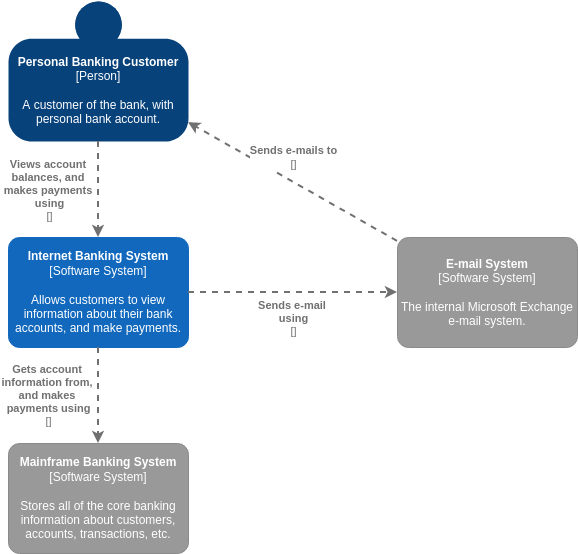
Reference Diagram: Image 4 (Primary) and Image 1 (Simplified View).
Analysis
The Internet Banking System sits within the boundary of the Big Bank plc enterprise. It acts as a digital channel for the Personal Banking Customer.
-
Users (Actors):
-
Personal Banking Customer: The primary user who interacts with the system to view balances and make payments.
-
Customer Service Staff: Bank employees who assist customers (shown in Image 4).
-
Back Office Staff: Administration and support staff (shown in Image 4).
-
-
External Systems:
-
Mainframe Banking System: The system of record. It stores all core banking information (customers, accounts, transactions). The Internet Banking System relies on this for authoritative data.
-
E-mail System: The internal Microsoft Exchange system used for sending notifications (e.g., password resets, confirmations) to customers.
-
ATM: A separate software system allowing cash withdrawals (shown in Image 4 to demonstrate the broader ecosystem).
-
Key Relationship: The customer interacts with the Internet Banking System, which in turn acts as a facade to the legacy Mainframe system to retrieve data and process payments.
3. Level 2: Container Diagram
Goal: To show the high-level technology choices and how responsibilities are distributed across the system.
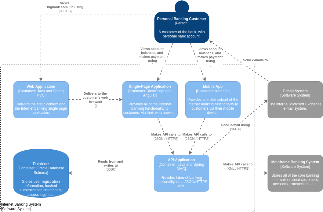
Reference Diagram: Image 2.
Analysis
The “Internet Banking System” from Level 1 is decomposed into five distinct containers (deployable units).
-
Web Application (Java and Spring MVC):
-
Role: Serves as the entry point for web users.
-
Function: Delivers static content (HTML/CSS/JS) and the Single-Page Application (SPA) to the customer’s browser via HTTPS.
-
-
Single-Page Application (JavaScript and Angular):
-
Role: The client-side logic running in the browser.
-
Function: Provides the full suite of internet banking functionality. It makes API calls to the backend.
-
-
Mobile App (Xamarin):
-
Role: The client-side application for mobile devices.
-
Function: Provides a limited subset of functionality compared to the web app. It also makes API calls to the backend.
-
-
API Application (Java and Spring MVC):
-
Role: The core backend logic.
-
Function: Exposes a JSON/HTTPS API. It handles authentication, business logic, and communication with external systems (Database, Mainframe, Email).
-
-
Database (Oracle Database Schema):
-
Role: Data persistence.
-
Function: Stores user registration info, hashed credentials, and access logs. Note: Core banking data remains in the Mainframe.
-
Key Relationship: Both the Web App (via the SPA) and the Mobile App communicate with the API Application. The API Application then talks to the Database for local data and the Mainframe for core banking data.
4. Level 3: Component Diagram
Goal: To zoom into a specific container (the API Application) to show its internal building blocks.
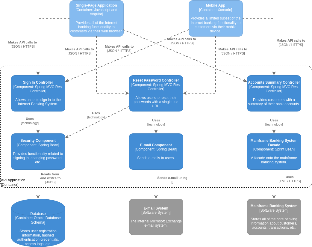
Reference Diagram: Image 3.
Analysis
This diagram breaks down the API Application container into logical components.
-
Controllers (Spring MVC Rest Controllers): These handle incoming HTTP requests.
-
Sign In Controller: Handles user authentication.
-
Reset Password Controller: Handles password recovery flows.
-
Accounts Summary Controller: Retrieves account data for the user.
-
-
Components (Spring Beans): These contain the business logic.
-
Security Component: Handles signing in and changing passwords. Used by the Sign In and Reset Password controllers.
-
E-mail Component: Handles sending emails. Used by the Reset Password controller.
-
Mainframe Banking System Facade: A wrapper around the external Mainframe system. It translates internal API calls to the XML/HTTPS format required by the legacy Mainframe. Used by the Accounts Summary Controller.
-
Key Relationship: The Accounts Summary Controller uses the Mainframe Banking System Facade to get data from the external Mainframe, demonstrating the separation of concerns between the API layer and the integration layer.
5. Level 4: Deployment Diagram
Goal: To show how the software containers map to physical infrastructure.
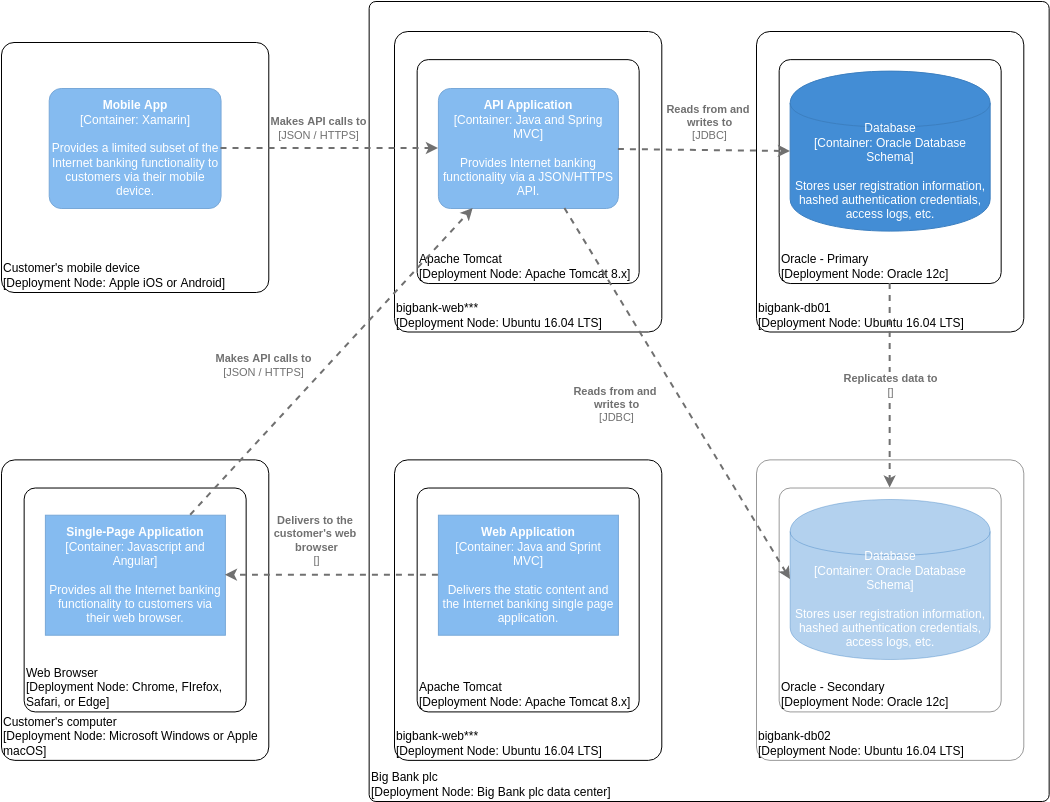
Reference Diagram: Image 5.
Analysis
This diagram illustrates the runtime environment.
-
Customer Side:
-
Mobile Device: Runs the Mobile App (iOS/Android).
-
Computer: Runs the Web Browser (Chrome/Firefox/Safari/Edge) which hosts the Single-Page Application.
-
-
Big Bank plc Data Center:
-
Web Servers (bigbank-web*):** Ubuntu 16.04 LTS nodes running Apache Tomcat 8.x.
-
Hosts the Web Application and API Application.
-
-
Database Servers (bigbank-db01/02): Ubuntu 16.04 LTS nodes running Oracle 12c.
-
Oracle – Primary: The main database.
-
Oracle – Secondary: A replica for redundancy/high availability.
-
-
Key Relationship: The Mobile App and Web Browser connect over the internet to the API Application hosted on Tomcat. The API Application connects via JDBC to the Oracle Database cluster.
6. Key Concepts and Guidelines Applied
Based on this case study, the following C4 modeling principles were applied:
-
Abstraction Levels: The model successfully moves from “Who uses it?” (Context) to “What is it built of?” (Containers) to “How is it organized?” (Components) to “Where does it run?” (Deployment).
-
Scope Boundaries:
-
In Level 1, the “Big Bank plc” boundary clearly distinguishes internal systems from external actors.
-
In Level 2, the “Internet Banking System” boundary encapsulates the specific software being built, separating it from the legacy Mainframe.
-
-
Separation of Concerns:
-
Frontend vs. Backend: The separation of the Single-Page Application (frontend) from the API Application (backend) allows for independent development and scaling.
-
Data Separation: Sensitive core banking data is kept in the Mainframe, while the Internet Banking System only caches necessary user access data in its own Oracle database.
-
-
Technology Agnosticism (where appropriate): The diagrams specify technologies (Java, Angular, Oracle) where they are relevant to the architecture decision, but focus primarily on the relationships and responsibilities of the blocks.
-
Notation: Standard C4 notation is used:
-
Person: Stick figures (or circles in this specific rendering style).
-
Software System/Container/Component: Rounded rectangles with distinct colors (Blue for internal/primary, Grey for external/secondary).
-
Relationships: Dashed arrows with labels describing the protocol (e.g., [HTTPS], [JSON], [JDBC]).
-