


Communication diagrams serve as a critical map for system interactions, yet they frequently suffer from structural decay. When loops become confusing or message flows turn ambiguous, the diagram ceases to function as a reliable specification. Instead, it becomes a source of misinterpretation that propagates errors into the development lifecycle. This guide provides a systematic approach to identifying and resolving these structural defects. We will focus on clarity, logical consistency, and semantic precision without relying on specific tooling features.
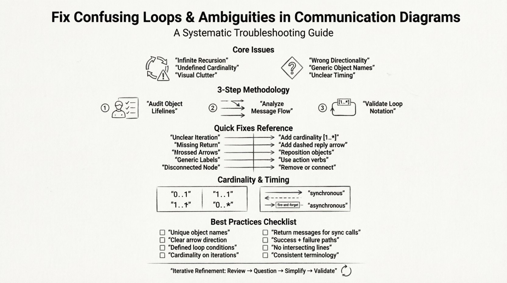
🧩 Understanding the Core Issues
Before applying fixes, one must understand the nature of the defects. Communication diagrams depict interactions between objects in a system. When these interactions are not clearly defined, the cognitive load on the reader increases significantly. This often leads to two primary categories of failure: loop confusion and interaction ambiguity.
🔄 The Problem with Loops
Loops represent iterative processes or recursive calls. In a diagrammatic context, they indicate that a message is sent multiple times or that an object refers back to itself. Confusion arises when the termination condition is missing or when the iteration count is unclear.
- Infinite Recursion: A message loop without a stop condition implies an infinite execution, which is rarely the intended design.
- Undefined Cardinality: If a loop is marked simply as “repeat” without specifying “1..*” or “0..1”, the frequency is unknown.
- Visual Clutter: Arrows that cross over each other to denote iteration can obscure the main flow.
❓ The Problem with Ambiguities
Ambiguity refers to elements that can be interpreted in more than one way. In a technical specification, there must be only one correct interpretation. Ambiguity often stems from poor labeling or missing context.
- Directionality: Arrows pointing in the wrong direction suggest a message flow that contradicts the actual data dependency.
- Object References: If an object is named generically, such as “Object 1”, it is impossible to trace its specific role.
- Timing: Without markers for synchronous versus asynchronous messages, the sequence of events is unclear.
🔍 Step-by-Step Troubleshooting Methodology
Resolving these issues requires a structured audit process. Do not attempt to fix everything at once. Follow this sequence to ensure comprehensive coverage of the diagram’s logic.
1. Audit the Object Lifelines
Every object involved in the interaction must be clearly defined. Start by verifying the identity of each participant.
- Check if every object has a unique, descriptive name.
- Ensure that the object’s role is consistent throughout the diagram.
- Verify that the object exists for the entire duration of the interaction or is created/destroyed explicitly.
2. Analyze the Message Flow
Messages are the verbs of your diagram. They drive the state changes. Scrutinize every arrow connecting the objects.
- Confirm that every arrow has a label describing the action.
- Ensure that return messages are indicated where necessary to show completion.
- Check for circular dependencies that do not serve a functional purpose.
3. Validate Loop Notation
Loops require specific notation to be understood correctly. Standard modeling conventions dictate how these should be represented.
- Use cardinality notations like
[1..*]for mandatory iterations. - Use
[0..1]for optional occurrences. - Clearly mark the guard condition if the loop depends on a specific state check.
📊 Common Scenarios and Fixes
The following table outlines frequent issues encountered during diagram review and the recommended corrective actions. Use this as a reference during your troubleshooting session.
| Scenario | Symptom | Recommended Fix |
|---|---|---|
| Unclear Iteration | Loop box lacks a count or condition. | Define cardinality (e.g., 1 to 5) or add a guard condition. |
| Missing Return Path | Message sent, but no reply shown. | Add a dashed return arrow with the response status. |
| Crossed Arrows | Multiple arrows intersect visually. | Reposition objects to minimize line crossings. |
| Generic Labels | Messages named “Process” or “Data”. | Use action verbs (e.g., “CalculateTax”, “ValidateUser”). |
| Disconnected Node | An object has no incoming or outgoing arrows. | Remove unused object or connect it to the relevant flow. |
📝 Refining Cardinality and Timing
Technical precision extends beyond simple connections. The metadata associated with the interactions carries significant weight. Cardinality defines the number of times an interaction occurs. Timing defines when it occurs.
Defining Cardinality
Cardinality is often the source of the most significant ambiguity. When a developer reads a diagram, they need to know if a loop runs once, multiple times, or never. Use the following standards to clarify this:
- 0..1: The interaction is optional. It may happen once or not at all.
- 1..1: The interaction is mandatory and happens exactly once.
- 1..*: The interaction is mandatory and happens at least once.
- 0..*: The interaction is optional and can happen any number of times.
Clarifying Timing
Timing indicates the synchronization of messages. Misunderstanding this can lead to race conditions in the implementation.
- Synchronous: The sender waits for a response before continuing. Represent this with a solid arrow and an explicit return message.
- Asynchronous: The sender continues without waiting. Represent this with a solid arrow and a distinct “fire-and-forget” label.
- Timing Markers: If specific delays are required, use timing constraints within the loop notation.
🛡️ Best Practices for Clarity
Avoiding these issues is better than fixing them later. Adopting these practices during the creation phase will reduce the need for extensive troubleshooting.
Consistent Naming Conventions
Naming is the first layer of clarity. If the names are inconsistent, the diagram becomes a puzzle rather than a map.
- Use nouns for objects (e.g.,
Customer,Order). - Use verbs for messages (e.g.,
Submit,Approve). - Keep the naming style consistent across all diagrams in the project.
Logical Grouping
Group related interactions together. Do not scatter messages across the canvas arbitrarily.
- Keep related objects close to each other to minimize line length.
- Use frames to group specific use cases or scenarios.
- Separate error handling flows from the happy path to reduce visual noise.
Review for Completeness
A diagram is incomplete if it only shows the success path. It must also account for failure modes.
- Include error messages in the loop if an exception might occur.
- Show how the system recovers from a timeout.
- Ensure that every exit point has a defined outcome.
🧪 Validation Checklist
Before finalizing a communication diagram, run it through this validation checklist. This ensures that the diagram is robust and ready for stakeholder review.
- ☐ Are all object names unique and descriptive?
- ☐ Is the direction of every arrow clear and correct?
- ☐ Do all loops have defined start and end conditions?
- ☐ Is the cardinality notation present on iterative messages?
- ☐ Are return messages included for synchronous calls?
- ☐ Does the diagram cover both success and failure scenarios?
- ☐ Are there any intersecting lines that obscure the flow?
- ☐ Is the terminology consistent with the rest of the documentation?
🔄 Iterative Refinement
Diagramming is rarely a one-time task. It is an iterative process of refinement. As the system design evolves, the diagrams must evolve with it. Regular reviews with the development team can catch ambiguities early. If a developer questions a message flow during a code review, it indicates an ambiguity in the diagram that needs immediate attention.
When you encounter a loop that cannot be simplified, consider breaking it down. Decomposing a complex interaction into smaller, sequential sub-diagrams can often resolve confusion better than trying to force everything onto a single canvas. This approach reduces cognitive load and makes the specific logic easier to follow.
📌 Summary of Key Takeaways
Communication diagrams are vital for understanding system behavior. However, they are prone to structural errors that hinder their effectiveness. By focusing on loop clarity, message directionality, and consistent notation, you can produce diagrams that serve as reliable specifications. The goal is precision, not decoration. Every line, label, and arrow must serve a functional purpose in describing the system’s logic.
Apply the troubleshooting steps outlined in this guide whenever you review a model. Verify the cardinality, check the object lifelines, and ensure that no ambiguity remains. A clear diagram saves time during development and reduces the risk of implementation errors. Prioritize readability and logical consistency above all else.