


Communication diagrams serve as a critical component in system architecture documentation. They depict the interactions between objects or parts in a Unified Modeling Language (UML) model. Unlike sequence diagrams, they focus primarily on the organization of objects and the relationships between them rather than the strict timing of messages. However, a diagram is only as good as its accuracy. If the model does not reflect the actual system behavior, implementation will fail or require expensive refactoring later.
Validation is not merely a final check; it is a continuous process that ensures the structural integrity of your design. This guide provides a rigorous checklist for validation. We will examine 15 specific areas that require attention. By following these steps, you ensure the integrity of your design before coding begins. This process helps identify logical gaps, missing links, and structural inconsistencies early in the development lifecycle.
Why Validation Matters 🔍
In software engineering, the cost of fixing an error increases exponentially as the project progresses. An error found during the design phase costs significantly less to resolve than one found during integration or testing. Communication diagrams bridge the gap between high-level requirements and low-level code. They define how data flows between components. When these connections are ambiguous or incorrect, the resulting application becomes fragile.
Validating these diagrams ensures that:
- Every required interaction is represented.
- Object relationships match the class structure.
- Message flows are logical and feasible.
- System boundaries are clearly defined.
Without this scrutiny, developers may implement logic that appears sound but fails under edge cases. The following checklist addresses the technical specifics of UML communication diagrams to prevent these issues.
The Validation Checklist 📋
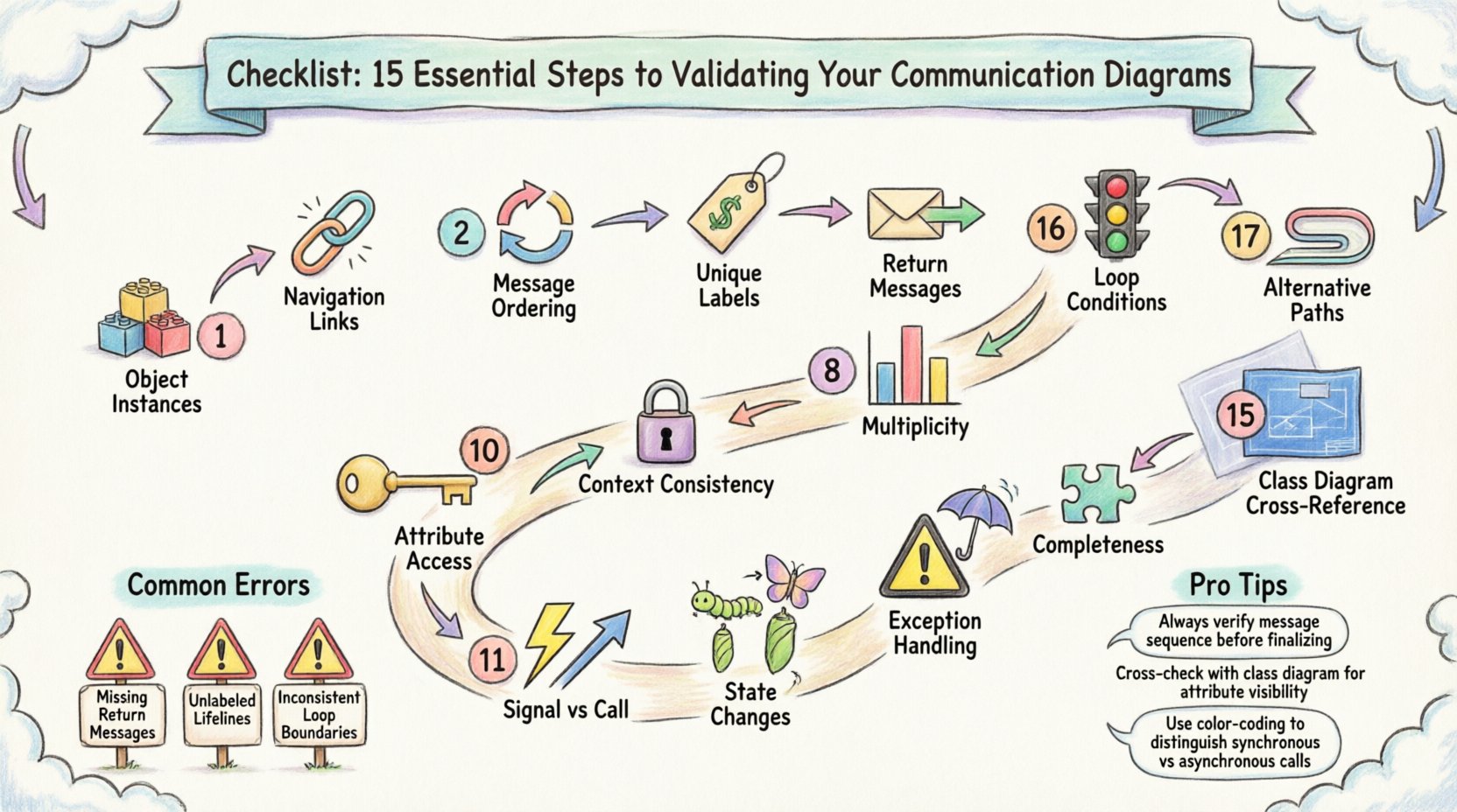
Below is the comprehensive list of 15 steps. Each step addresses a specific aspect of the diagram. You should review your diagrams against these criteria systematically.
1. Verify Object Instances and Lifelines 🧱
Ensure that every object depicted in the diagram actually exists in the system architecture. Sometimes designers add objects to facilitate a flow that does not technically exist in the codebase. Check the Class Diagram to confirm that every participant in the communication diagram is a valid class or interface. If an object is missing from the class model, the interaction is impossible.
- Confirm class names match exactly.
- Ensure no phantom objects are created.
- Verify that object roles match their class responsibilities.
2. Check Navigation Links Between Objects 🔗
Communication diagrams rely on links to show how objects find each other. A message cannot be sent unless a link exists. Validate that every arrow in your diagram corresponds to a navigable path in the code. If Object A sends a message to Object B, Object A must have a reference to Object B.
- Trace the link from the sender to the receiver.
- Ensure references are established in the constructor or dependency injection.
- Check for circular dependencies that might break initialization.
3. Validate Message Ordering and Flow 🔄
While sequence diagrams emphasize time, communication diagrams imply order through the numbering of messages. Verify that the sequence numbers reflect the actual execution flow. A message labeled 1.1 must be completed or initiated before 1.2. Ensure there are no logical loops that create infinite recursion without a termination condition.
- Check that message numbers are sequential.
- Ensure no message is called before its prerequisite is fulfilled.
- Verify that return messages are placed correctly relative to the call.
4. Ensure Unique Message Labels 🏷️
Ambiguity is the enemy of implementation. If two messages share the same label but have different parameters or return types, the developer will not know which method to invoke. Check that every message label is unique within the context of the sender object. Use descriptive names that clearly indicate the action.
- Review method signatures for duplicates.
- Ensure parameter lists are distinct if method names are similar.
- Clarify if an action is a getter, setter, or business logic handler.
5. Confirm Return Messages (Explicit vs Implicit) 📤
Communication diagrams often omit return messages for brevity, but this can lead to confusion regarding asynchronous operations. Decide whether to show return values explicitly. If a method is synchronous, ensure the flow waits for the response. If asynchronous, the diagram should reflect the fire-and-forget nature without blocking the sender.
- Mark synchronous calls clearly.
- Indicate asynchronous signals with appropriate notation.
- Ensure the caller knows when to expect a result.
6. Review Loop Conditions (Iteration Logic) 🔁
Complex systems often involve processing collections of data. If your diagram shows a loop, validate the condition that controls it. Does the loop terminate? What is the exit criteria? An infinite loop in the design leads to an infinite loop in the code, causing system hangs.
- Check for “while” or “for” loop notations.
- Verify the counter or condition variable is updated.
- Ensure the loop does not exceed system resource limits.
7. Check Alternative Paths (If/Else Logic) 🚦
Real-world systems handle exceptions and variations. A single path does not represent reality. Validate that alternative branches are documented. If a condition fails, where does the flow go? Ensure that error handling paths are included in the diagram, not just the happy path.
- Identify all decision points.
- Map the “then” and “else” outcomes.
- Ensure no path leads to a dead end without error handling.
8. Validate Object Multiplicity (Cardinality) 📊
Multiplicity defines how many instances of an object can be involved. Does the diagram assume a single instance where multiple are possible? Check the link labels for cardinality (e.g., 1, 0..*, 1..*). This affects how collections are handled in the implementation.
- Verify 1-to-1 relationships are strictly single.
- Ensure 1-to-many relationships handle collections correctly.
- Check that null values are handled according to the cardinality.
9. Ensure Context Consistency (Start/End Points) ⏳
Every interaction has a start and an end. Verify that the diagram has a clear entry point. Is it triggered by a user event, a system timer, or another service? Ensure the termination condition is clear. An open-ended interaction implies a long-running process that may need state management.
- Define the trigger event clearly.
- Identify the final state of the objects.
- Check for resource leaks at the end of the process.
10. Verify Attribute Access and Method Calls 🔑
Objects interact by invoking methods or accessing attributes. Validate that the methods called actually exist in the target class. Check visibility modifiers (public, private, protected). A public object cannot access a private method of another object without a public interface or setter.
- Match method names to the source code.
- Check visibility permissions.
- Ensure parameter types match the method signature.
11. Check Signal vs. Call Messages (Synchronous vs Asynchronous) ⚡
Distinguish between a standard call and a signal. A call expects a response; a signal does not. Confusing these leads to threading issues. If the system is concurrent, ensure asynchronous signals are used for non-blocking operations.
- Label synchronous calls as standard arrows.
- Label asynchronous signals with open arrowheads.
- Ensure the system design supports the chosen concurrency model.
12. Review State Changes (Object Transitions) 🔄
Objects change state during interactions. Does the diagram reflect these changes? For example, an order object might move from “Pending” to “Confirmed” after a payment message. While state diagrams are better for this, the communication diagram should imply the state change.
- Identify state transitions for key objects.
- Ensure the new state is consistent with the action.
- Check if the state change triggers further messages.
13. Validate Exception Handling (Error Paths) ⚠️
Systems fail. The diagram should not only show success. Validate that exception messages are present. If a database connection fails, does the diagram show the error propagation? Without this, the code will crash silently or throw unhandled exceptions.
- Include error return messages.
- Define how errors are logged or notified.
- Ensure recovery mechanisms are mapped.
14. Confirm Completeness (All Required Interactions Present) 🧩
It is common to omit interactions that seem obvious. However, “obvious” is subjective. Review the requirements document. Does the diagram cover every functional requirement? Missing a single interaction can break a feature completely.
- Cross-reference with the requirements specification.
- Ensure all API endpoints are covered.
- Verify all data inputs and outputs are accounted for.
15. Cross-Reference with Class Diagram (Structure Consistency) 🏗️
The communication diagram is a behavioral view, but it rests on the structural view of the Class Diagram. Ensure there is no contradiction. If the Class Diagram says a class has no attribute, the communication diagram cannot show it being accessed. Maintain consistency across all UML artifacts.
- Compare attribute lists between diagrams.
- Verify inheritance hierarchies are respected.
- Ensure interface implementations are correct.
Common Validation Errors Table 📋
| Issue Type | Description | Impact | Fix |
|---|---|---|---|
| Orphaned Links | A message sent without a navigable link. | Runtime Reference Error | Add the link to the class structure. |
| Missing Returns | Call made without expected return data. | Null Pointer Exception | Verify return type and add return message. |
| Circular Dependency | Object A calls B, B calls A immediately. | Stack Overflow | Refactor to decouple the objects. |
| Invalid Multiplicity | Assuming one object where many exist. | Logic Errors | Update to collection handling in code. |
| Visibility Mismatch | Calling a private method. | Compilation Error | Make method public or add getter. |
Implementation Tips for Validation 🔧
Once the checklist is complete, consider applying these practical techniques to reinforce your validation process.
Peer Review Sessions
Have a colleague review the diagram. A fresh pair of eyes often spots missing links or ambiguous labels that the creator missed. Encourage them to trace the flow on paper before looking at the code.
Automated Consistency Checks
Many modeling tools offer validation features. Use these to detect syntax errors, such as missing labels or broken links. However, do not rely solely on the tool. It checks syntax, not business logic.
Traceability Matrix
Create a matrix linking requirements to diagram messages. If a requirement has no corresponding message in the diagram, it is incomplete. This ensures nothing is forgotten during the translation from design to code.
Final Thoughts on Design Integrity 🛡️
Validating a communication diagram is about ensuring that the visual representation matches the reality of the software. It requires attention to detail and a deep understanding of the system architecture. By following these 15 steps, you reduce the risk of defects entering the codebase. The effort invested in this phase pays dividends during the testing and deployment stages. A well-validated diagram serves as a reliable contract between the design team and the development team, ensuring that the final product aligns with the intended design.
Remember that diagrams are living documents. As the system evolves, the communication diagrams must be updated to reflect new interactions. Treat them as essential documentation, not just a one-time activity. This discipline leads to more robust, maintainable, and scalable software systems.