


Designing complex software systems requires more than just writing code. It demands a clear vision of how different parts of the application interact, depend on one another, and remain isolated when necessary. This is where a package diagram becomes an essential tool. A package diagram allows architects and developers to visualize the high-level organization of a system, breaking down intricate logic into manageable modules. Whether you are refactoring legacy code or designing a new microservices architecture, understanding how to construct these diagrams from the ground up is a critical skill.
This guide provides a comprehensive, step-by-step approach to creating clear package diagrams. We will explore the principles of modular design, the semantics of relationships, and the best practices for maintaining readability over time. No specific software tools are required to understand these concepts; the focus remains on the logic and structure of the architecture itself.
Why Use Package Diagrams? 🤔
Before diving into the construction process, it is vital to understand the value proposition. A package diagram is not merely a drawing; it is a communication device. It serves multiple purposes within a development lifecycle:
- Clarity in Complexity: Large systems can become overwhelming. Package diagrams reduce this complexity by grouping related elements together.
- Dependency Management: They make visible where one module relies on another, helping to prevent circular dependencies and tight coupling.
- Documentation: They provide a static reference point for new team members to understand the system boundaries quickly.
- Planning: They allow architects to plan for scalability before writing a single line of implementation code.
Without a clear visual representation, codebases can drift into a state of high coupling, where changing one component breaks others unexpectedly. A well-constructed package diagram acts as a map, guiding developers through the structural landscape.
Phase 1: Preparation and Scope Definition 📝
The foundation of any good diagram is preparation. You cannot draw a map without knowing the territory. In this phase, you define what the diagram will cover and what it will exclude.
1.1 Identify the Boundary
Decide the scope of the system you are modeling. Is it the entire enterprise application? A specific microservice? A library? Defining the boundary early prevents scope creep. If you try to include everything, the diagram will become cluttered and lose its utility.
1.2 Gather Existing Information
Before drawing, collect relevant artifacts. Look for:
- Existing code repositories and module structures.
- Architecture decision records (ADRs).
- Database schema definitions.
- API specifications.
These documents provide the raw data needed to infer the logical grouping of your system.
1.3 Define the Audience
Who will read this diagram? A technical lead needs different details than a project manager. If the audience is technical, include interface names and dependency types. If the audience is management, focus on high-level modules and data flow without getting bogged down in technical syntax.
Phase 2: Identifying and Grouping Packages 🧩
This is the core of the diagramming process. You are moving from raw code or requirements to logical groupings. The goal is to create packages that are cohesive and loosely coupled.
2.1 The Principle of Cohesion
Cohesion refers to how closely related the elements within a package are. A package should contain elements that work together to achieve a single, well-defined purpose. If a package contains unrelated functionality, it lacks cohesion.
High Cohesion Example: A package named Authentication containing login logic, token generation, and password hashing.
Low Cohesion Example: A package named SystemCore containing database access, user interface rendering, and email sending.
2.2 The Principle of Coupling
Coupling refers to the degree of interdependence between software modules. You want low coupling. If Package A needs to know the internal details of Package B to function, they are tightly coupled. Ideally, they should interact through well-defined interfaces.
2.3 Grouping Strategies
There are several ways to group elements into packages. Choose the one that fits your project structure best.
- By Function: Group by what the code does (e.g.,
Reporting,Billing,Notification). - By Layer: Group by architectural layer (e.g.,
UI,Business Logic,Data Access). - By Domain: Group by business domain (e.g.,
Customer,Product,Order). - By Technology: Group by the underlying technology stack (e.g.,
Database,Web Server,Cache).
Recommendation: For most modern systems, grouping by Domain or Function provides the best balance of maintainability and clarity.
Phase 3: Defining Relationships 🔗
Once packages are created, you must define how they connect. These relationships indicate the flow of data and control. There are four primary relationship types to understand.
3.1 Dependency
A dependency exists when one package uses another but does not depend on its internal structure. It is a “uses” relationship. In a diagram, this is often represented by a dashed arrow.
- Use Case: The
OrderServicepackage uses thePaymentGatewaypackage to process transactions. - Implication: If the
PaymentGatewaychanges its internal implementation but keeps the same interface,OrderServiceremains unaffected.
3.2 Association
An association represents a structural relationship where one package holds a reference to another. It implies a stronger connection than a dependency.
- Use Case: A
Customerpackage holds a list ofOrderobjects. - Implication: The lifecycle of the associated object may be tied to the owner.
3.3 Generalization (Inheritance)
This relationship indicates that one package is a specialized version of another. It represents an “is-a” relationship.
- Use Case: A
AdminUserpackage extends the functionality of aBaseUserpackage. - Implication: Changes to the base package propagate to the specialized package.
3.4 Realization (Interface Implementation)
This occurs when a package implements an interface defined by another package. It allows for polymorphism.
- Use Case: A
SqlRepositorypackage realizes aDataStoreinterface. - Implication: The implementation can be swapped without affecting the consumer.
| Relationship Type | Semantics | Visual Notation | Best Practice |
|---|---|---|---|
| Dependency | Uses functionality | Dashed Arrow | Minimize to reduce coupling |
| Association | Structural link | Solid Line | Define clearly |
| Generalization | Inheritance | Solid Line with Triangle | Use for hierarchy |
| Realization | Interface implementation | Dashed Line with Triangle | Use for abstraction |
Phase 4: Refinement and Naming 🏷️
A diagram with correct relationships but poor naming is useless. Names must be intuitive, consistent, and descriptive. This phase focuses on polishing the visual output.
4.1 Naming Conventions
Consistency is key. Adopt a standard naming convention and stick to it throughout the project. Common practices include:
- PascalCase:
OrderProcessing,UserManagement. - CamelCase:
orderProcessing,userManagement. - Underscores:
order_processing,user_management.
Avoid generic names like Module1, Logic, or Data. These provide no context to the reader.
4.2 Labeling Relationships
Not all arrows need labels, but those that do should be specific. Instead of labeling an arrow simply as “uses”, consider labeling it with the specific action, such as “queries” or “saves”. This adds semantic value to the diagram.
4.3 Visual Hierarchy
Use visual cues to indicate importance or priority. You might:
- Place core packages in the center.
- Place peripheral or utility packages on the edges.
- Use distinct colors for different layers (e.g., UI, Business, Data).
Ensure the diagram is not a chaotic web of lines. Arrange packages so that dependencies flow logically, typically from top to bottom or left to right.
Phase 5: Review and Validation ✅
Once the diagram is drafted, it must undergo a review process. This ensures accuracy and adherence to architectural standards.
5.1 The Dependency Rule
Apply the Dependency Rule strictly. This rule states that source code dependencies must point only inward. The innermost package should not depend on any outer package. This ensures that core logic remains stable and independent of external frameworks or infrastructure.
5.2 Check for Cycles
Circular dependencies occur when Package A depends on Package B, and Package B depends on Package A. This creates a loop that makes the system hard to test and maintain. Scan your diagram for closed loops and resolve them by extracting shared logic into a third package or using interfaces.
5.3 Peer Review
Have a colleague review the diagram. Ask them:
- Can you understand the system boundary without reading documentation?
- Are the relationships clear?
- Is the naming consistent?
Feedback from a fresh perspective often reveals ambiguities you missed during creation.
Common Pitfalls to Avoid 🚫
Even experienced architects make mistakes. Being aware of common pitfalls can save you time and prevent technical debt.
- Over-Abstraction: Creating too many levels of abstraction. A package diagram should not be a map of maps. Keep the hierarchy shallow.
- Ignoring Interfaces: Drawing dependencies between concrete classes instead of interfaces. This leads to tight coupling.
- Static Snapshots: Treating the diagram as a one-time task. Architecture evolves. If the code changes, the diagram must change.
- Too Much Detail: Trying to show every single class in a package diagram. This is a class diagram’s job. Package diagrams should remain high-level.
- Ignoring Cross-Cutting Concerns: Failing to account for logging, security, or monitoring. These often span multiple packages and should be represented as distinct cross-cutting packages or layers.
Maintaining the Diagram Over Time 🔄
A diagram that is outdated is worse than no diagram at all. It creates false confidence. To keep your package diagrams accurate:
- Integrate into CI/CD: Use tools to automatically generate diagrams from the codebase if possible. This ensures the diagram matches the code.
- Review During PRs: Make diagram updates a requirement for Pull Requests that change architectural boundaries.
- Version Control: Store diagram files in the same repository as the code. This ensures they are versioned and tracked together.
- Regular Audits: Schedule quarterly reviews to ensure the architecture still matches the business goals.
Advanced Scenarios 🔬
As your system grows, you may encounter complex scenarios that require advanced diagramming techniques.
7.1 Subsystems and Views
When a system becomes too large for a single diagram, break it down into subsystems. Create a master overview diagram that shows the major subsystems, and then create detailed diagrams for each subsystem. This is similar to a table of contents for your architecture.
7.2 External Dependencies
Clearly mark external systems. Use a specific visual style (like a dashed box) to indicate that a package relies on a third-party service or an external database. This helps developers understand the system’s reliance on outside infrastructure.
7.3 Concurrency and State
While package diagrams are primarily structural, they can hint at state management. If a package manages global state, indicate this in the notes or through specific labeling. This warns consumers that concurrent access might be a concern.
Conclusion on Best Practices 🌟
Creating clear package diagrams is a disciplined process. It requires a deep understanding of the system, a commitment to consistency, and a willingness to refactor both code and documentation. By following the steps outlined in this guide—defining scope, grouping logically, defining relationships, refining names, and validating structure—you can produce diagrams that serve as reliable blueprints for your software.
Remember that the goal is not perfection on the first attempt. It is clarity. A diagram that is slightly imperfect but clearly communicates the structure is far more valuable than a perfect diagram that is confusing to read. Start small, iterate often, and let the diagram evolve alongside your code.
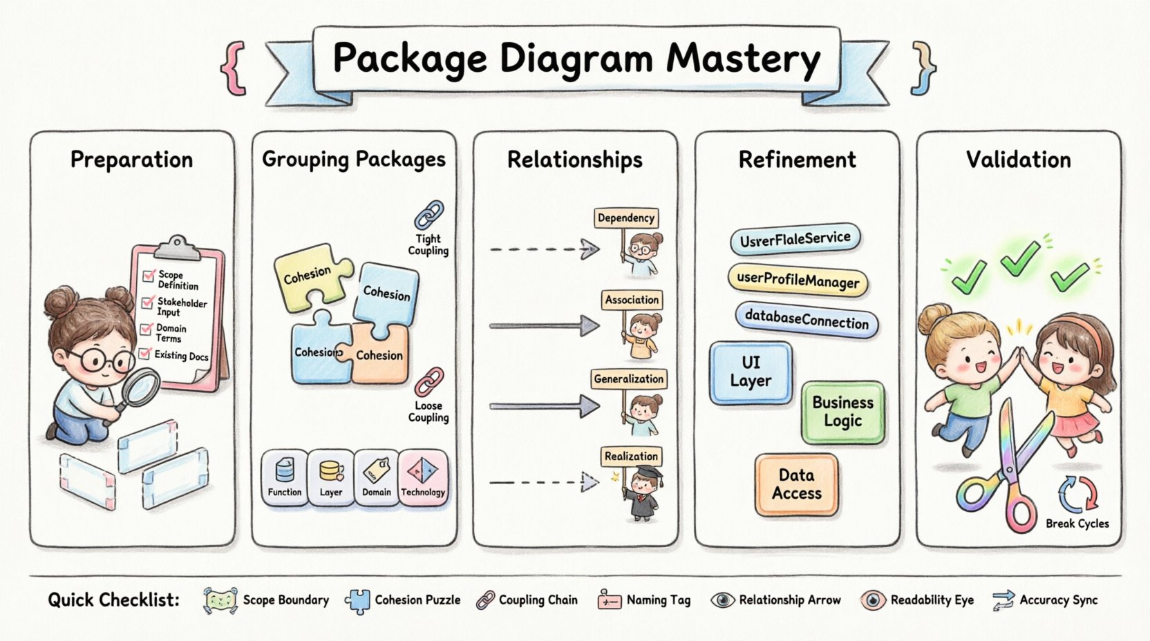
Quick Reference Checklist 📋
- Scope: Is the boundary clear?
- Cohesion: Does each package do one thing well?
- Coupling: Are dependencies minimized and directed inward?
- Naming: Are package names descriptive and consistent?
- Relationships: Are arrows labeled and accurate?
- Readability: Is the layout logical and uncluttered?
- Accuracy: Does this match the current codebase?
By keeping this checklist handy during your design sessions, you can ensure that your package diagrams remain a valuable asset throughout the lifecycle of your project.