

Understanding the structural integrity of complex software systems requires more than just examining individual classes or functions. It demands a higher level of abstraction. This is where the package diagram serves its purpose. A package diagram groups related elements into containers, providing a macroscopic view of the system architecture. It allows engineers to visualize dependencies, manage namespaces, and clarify the boundaries between different modules. Without this structural clarity, large-scale projects risk becoming entangled in a web of dependencies that are difficult to maintain or refactor.
This guide explores the core mechanics of package diagrams. We will dissect the elements that constitute these diagrams, examine the relationships that connect them, and discuss the principles that ensure a robust design. By the end, you will have a clear understanding of how to organize code, manage complexity, and communicate architectural decisions effectively.
🔍 What is a Package Diagram?
At its core, a package diagram is a type of structural diagram used in system modeling. It represents the organization of a system by grouping elements into packages. A package is essentially a namespace that collects related elements together. This grouping reduces complexity by hiding internal details and exposing only the necessary interfaces to other parts of the system.
Think of a package as a folder in an operating system, but with stricter rules. In software engineering, packages often correspond to directories in a file system, but they also represent logical boundaries. For example, a package might contain all classes related to user authentication, while another package holds all database connection logic. This separation ensures that changes in one area do not inadvertently break functionality in another.
The primary benefits of using package diagrams include:
- Complexity Reduction: By grouping elements, you reduce the cognitive load required to understand the system.
- Dependency Management: You can clearly see which parts of the system rely on others.
- Modularity: Packages encourage the creation of independent units that can be developed and tested separately.
- Scalability: As the system grows, new packages can be added without disrupting existing structures.
🧱 Core Elements of a Package Diagram
To construct a meaningful package diagram, one must understand the specific elements that make up the visual language. Each component serves a distinct function in communicating the architecture.
1. Packages
The package itself is the fundamental building block. Visually, it is often represented as a rectangle with a tab on the top left corner. The label inside indicates the name of the package. In many modeling standards, the name should be unique within the context of the diagram.
- Name: Identifies the package. It often follows a naming convention, such as reverse domain name notation (e.g.,
com.example.module). - Contents: The package can contain other packages, classes, interfaces, or components. This nesting capability allows for hierarchical organization.
- Stereotypes: Packages can be tagged with stereotypes to indicate their role, such as <
>, < >, or < >.
2. Relationships
Relationships define how packages interact with one another. These lines are crucial because they represent the flow of information or dependency between modules. Mismanaged relationships can lead to tight coupling, which makes the system brittle.
3. Stereotypes and Tags
Stereotypes provide additional context to standard elements. For instance, a package might be marked as <
🔗 Understanding Package Relationships
The power of a package diagram lies in the connections between packages. These connections dictate the architecture of the system. There are several standard types of relationships, each with specific implications for system behavior and maintenance.
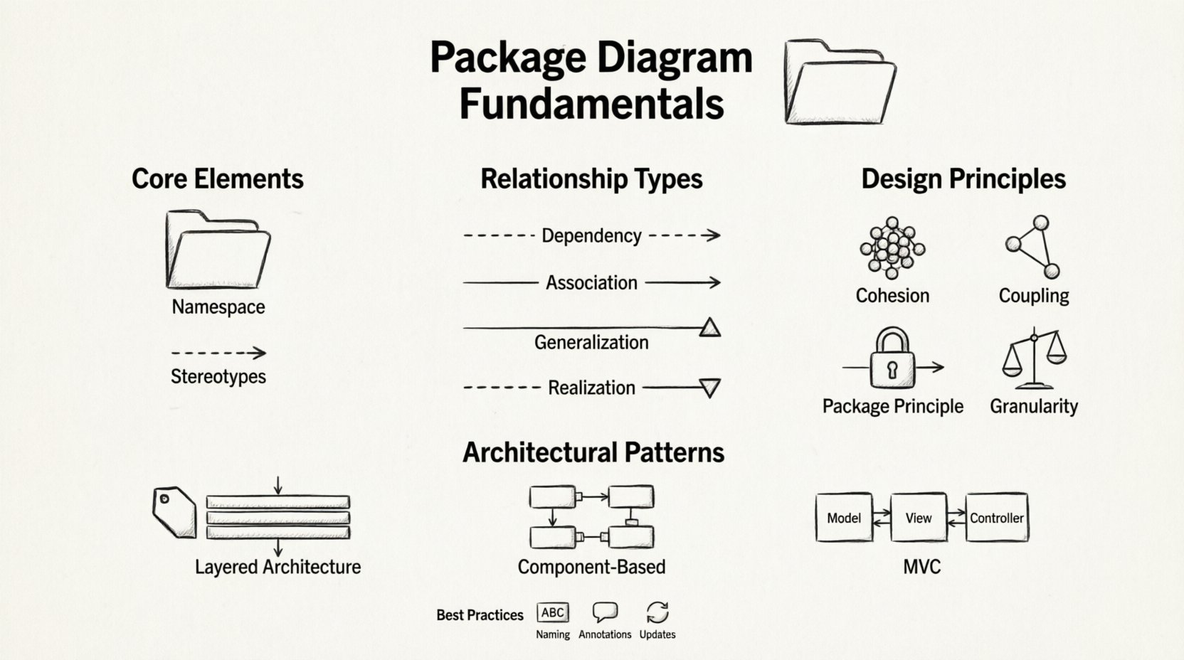
Dependency
A dependency relationship exists when a change in the specification of one package affects the functionality of another. This is the most common relationship in software systems. It is often represented by a dashed arrow pointing from the dependent package to the package being depended upon.
- Implication: The dependent package cannot function correctly without the supplier package.
- Example: A
Reportingpackage depends on aDataAccesspackage to retrieve information. - Best Practice: Minimize dependencies to reduce coupling. High coupling makes testing difficult.
Association
An association represents a structural link between packages. Unlike dependencies, which are often transient or usage-based, associations imply a stronger, often permanent, link. In package diagrams, this is less common than in class diagrams but still relevant when packages share resources.
- Direction: Can be unidirectional or bidirectional.
- Visibility: Indicates which packages have access to the internals of another.
Generalization (Inheritance)
Generalization represents a “is-a” relationship between packages. While more common with classes, it can apply to packages if one package is a specialized version of another. This is often seen in layered architectures where a lower layer provides a general interface and a higher layer extends it.
- Visual: A solid line with a hollow triangle arrowhead pointing to the superclass.
- Use Case: Extending a core framework package with domain-specific logic.
Realization (Interface Implementation)
Realization occurs when a package implements the contract defined by another package. This is critical for defining interfaces. It ensures that a package adheres to a specific set of rules or behaviors defined by an interface package.
- Visual: A dashed line with a hollow triangle arrowhead.
- Benefit: Promotes loose coupling by allowing packages to interact through interfaces rather than concrete implementations.
📊 Comparison of Relationship Types
Choosing the right relationship is vital for a clean architecture. The table below summarizes the differences to aid in decision-making.
| Relationship | Visual Notation | Meaning | Impact on Coupling |
|---|---|---|---|
| Dependency | Dashed Arrow | One package uses another | High (if excessive) |
| Association | Solid Line | Structural link between packages | Medium |
| Generalization | Solid Line + Triangle | Specialization of a package | Low (if used correctly) |
| Realization | Dashed Line + Triangle | Implementation of an interface | Low (Promotes decoupling) |
🛠️ Principles of Effective Package Design
Creating a package diagram is not just about drawing boxes and lines. It requires adherence to design principles that ensure the system remains maintainable over time. These principles guide how packages should be grouped and how they should interact.
1. Cohesion
Cohesion refers to how closely related the elements within a package are. A highly cohesive package contains elements that work together to achieve a single, well-defined purpose. If a package contains unrelated classes, it has low cohesion.
- High Cohesion: Makes the package easier to understand and test.
- Low Cohesion: Leads to confusion and unintended side effects when changes are made.
2. Coupling
Coupling measures the degree of interdependence between packages. Low coupling is generally desirable. It means that a package can be changed or replaced without significantly affecting other parts of the system.
- Loose Coupling: Achieved through interfaces and minimal dependencies.
- Tight Coupling: Occurs when packages rely heavily on internal details of other packages.
3. The Package Principle
This principle suggests that packages should be closed to modification but open to extension. While this sounds like a class-level principle, it applies to packages as well. A package should expose a stable interface that other packages can use, while hiding its internal implementation.
4. Consistent Granularity
All packages in a diagram should be roughly of the same size and complexity. Mixing very large subsystems with tiny utility packages creates an imbalance. It makes it difficult to manage the build process and deployment.
🏗️ Architectural Patterns and Package Organization
There are standard ways to organize packages that align with common architectural patterns. Adopting these patterns can save time and provide a familiar structure for developers joining the project.
Layered Architecture
In a layered architecture, packages are organized into horizontal layers. Each layer provides services to the layer above it and uses services from the layer below. For example:
- Presentation Layer: Handles user interaction.
- Business Logic Layer: Contains core rules and calculations.
- Data Access Layer: Manages storage and retrieval.
Dependencies should only flow downwards. The presentation layer depends on business logic, which depends on data access. Reverse dependencies create cycles and tight coupling.
Component-Based Architecture
Here, packages represent independent components. Each component encapsulates a specific functionality. They communicate through well-defined interfaces. This pattern is ideal for distributed systems or microservices.
- Independence: Components can be deployed separately.
- Reusability: Components can be used in different parts of the system.
MVC Pattern
The Model-View-Controller pattern separates concerns into three distinct packages:
- Model: Represents the data and business rules.
- View: Handles the display of information.
- Controller: Processes input and updates the model or view.
This separation allows developers to modify the UI without touching the business logic.
🚧 Managing Complexity and Challenges
Even with good principles, package diagrams can become complex. Engineers often face specific challenges when modeling large systems. Recognizing these challenges early helps in mitigating risks.
Circular Dependencies
A circular dependency occurs when Package A depends on Package B, and Package B depends on Package A. This creates a cycle that can prevent the system from compiling or running correctly.
- Problem: It makes it impossible to determine the initialization order.
- Solution: Extract the shared code into a third package that both A and B depend on, breaking the cycle.
Package Spaghetti
This term describes a situation where packages are interconnected in a messy web of dependencies. It usually happens when dependencies are added ad-hoc without a plan.
- Symptom: Changing one package causes failures in unexpected places.
- Solution: Refactor to reduce dependencies. Use interfaces to decouple logic.
Versioning Conflicts
When packages evolve, versioning becomes an issue. If Package A updates its interface and Package B is still using the old version, the system breaks.
- Strategy: Use semantic versioning for packages.
- Strategy: Maintain backward compatibility as long as possible.
📝 Best Practices for Documentation
A package diagram is not just a design tool; it is documentation. It serves as a map for developers who are not involved in the initial design. Clear documentation ensures that the knowledge is preserved.
Naming Conventions
Consistent naming is essential. Use a standard convention that reflects the domain of the application. Avoid generic names like Package1 or ModuleA.
- Example:
UserManagementinstead ofModule1. - Benefit: Makes the diagram self-explanatory.
Annotation and Comments
Not every relationship needs to be explained, but critical dependencies should be annotated. Use notes to explain why a dependency exists or what constraints apply.
- Note: “This dependency is legacy and will be removed in the next sprint.”
- Note: “This package is read-only for external systems.”
Regular Updates
A diagram is only useful if it matches the current state of the code. Outdated diagrams can mislead developers and waste time.
- Practice: Update the diagram during the code review process.
- Practice: Automate generation where possible to keep it in sync with the source code.
🔄 Integration with Other Diagrams
Package diagrams do not exist in isolation. They work in conjunction with other diagrams to provide a complete picture of the system.
Class Diagrams
Package diagrams often serve as the container for class diagrams. A package may contain multiple class diagrams. The package diagram shows how the groups of classes relate to each other, while the class diagram shows the details within the group.
Component Diagrams
Component diagrams are similar but focus on runtime artifacts. Package diagrams focus on static structure. The transition from package to component often happens during the implementation phase.
Deployment Diagrams
Deployment diagrams show where packages are physically deployed. A package might be split across multiple nodes in a deployment diagram if it is distributed. Understanding this link helps in planning infrastructure.
🔎 Troubleshooting Common Issues
When reviewing a package diagram, look for specific signs of poor design. These indicators suggest that refactoring is needed.
- Too many dependencies: If a package depends on more than 10 other packages, it is likely doing too much.
- Large packages: A package with hundreds of classes should be split into smaller sub-packages.
- Inconsistent naming: If some packages use nouns and others use verbs, it indicates a lack of standardization.
- Hidden dependencies: If dependencies are implied but not drawn, the diagram is incomplete.
🚀 Moving Forward
Designing package diagrams is a skill that improves with practice. It requires a balance between technical detail and high-level abstraction. As systems grow, the ability to organize code into logical packages becomes increasingly critical. It allows teams to work in parallel without stepping on each other’s toes.
Start small. Create a simple package structure for your current project. Identify the main domains of functionality. Group related classes together. Draw the relationships. Review the diagram with your team. Does it make sense? Is it easy to understand? If the answer is yes, you have built a solid foundation. If not, iterate. Refine the boundaries. Adjust the dependencies.
Remember that the goal is clarity. A diagram that confuses the reader is as bad as no diagram at all. Focus on reducing cognitive load. Use standard notations. Keep relationships simple. By adhering to these fundamentals, you create a system that is robust, maintainable, and scalable.
Continuous improvement is key. Revisit your package structure periodically. Technology changes, requirements change, and so should your architecture. Keep your diagrams up to date. Let them serve as a living map of your system’s evolution.