


Creating a clear visual representation of your system architecture is a fundamental skill for any developer or architect. A package diagram provides a high-level overview of the structural organization of a system. It allows you to group related elements into logical units, manage dependencies, and understand the boundaries between different modules. This guide walks you through the process of creating your first package diagram without relying on specific tools, focusing instead on the underlying principles and logical steps required for effective modeling.
🤔 What Is a Package Diagram?
A package diagram is a type of structural diagram used in modeling languages to organize system components. Unlike class diagrams that focus on individual objects and methods, package diagrams operate at a higher level of abstraction. They are designed to handle complexity by grouping classes, interfaces, and other packages into manageable clusters. This clustering helps in maintaining separation of concerns and reduces the cognitive load when analyzing the overall system design.
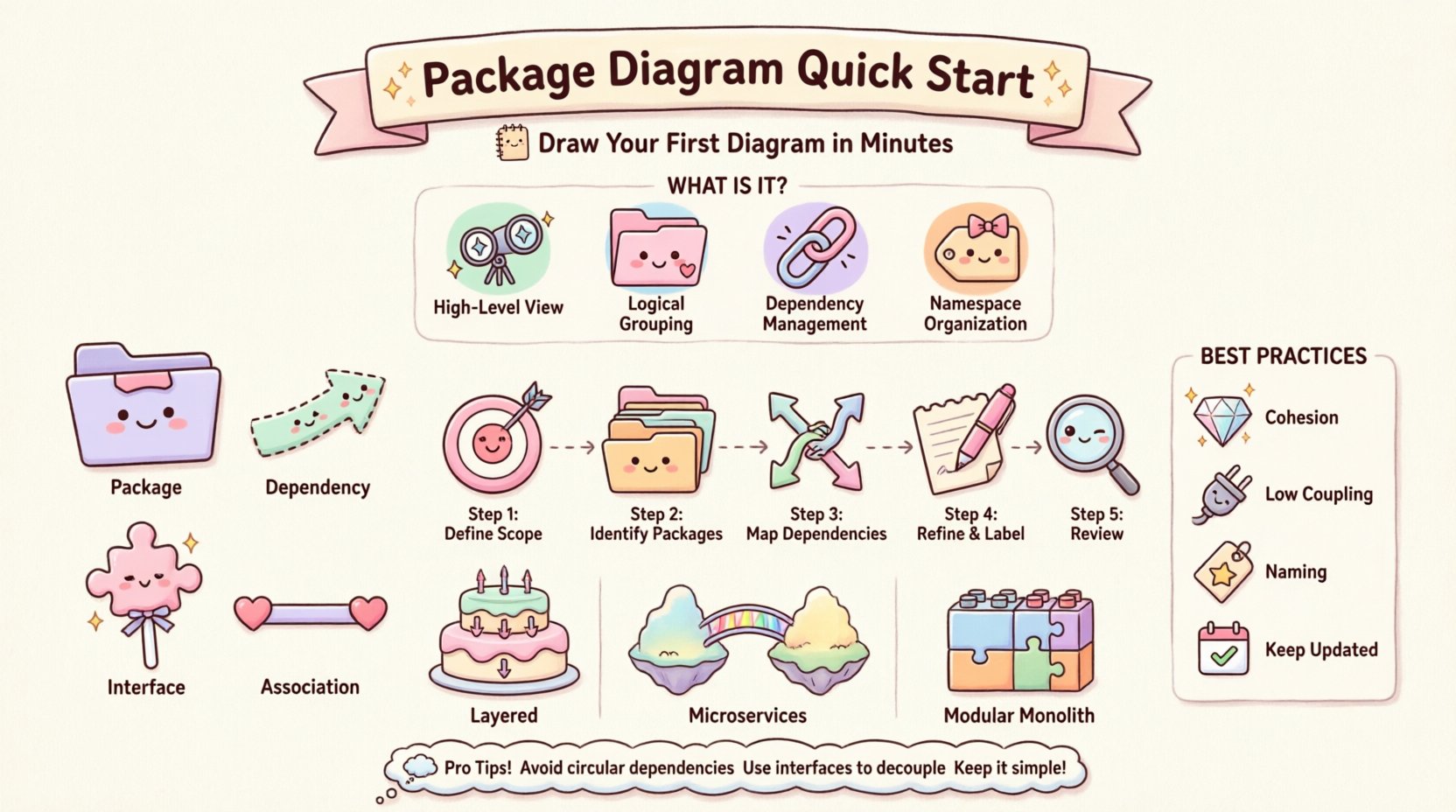
- High-Level View: It offers a macro perspective rather than micro-details.
- Logical Grouping: It organizes elements based on functionality or layer.
- Dependency Management: It visualizes how different parts of the system interact.
- Namespace Organization: It defines boundaries for namespaces in code.
Understanding the purpose of this diagram is crucial before drawing lines and boxes. The goal is not merely to create an image but to document the architectural intent of the software. This documentation serves as a reference for onboarding new team members, planning refactoring efforts, and ensuring that the system remains scalable over time.
🛠️ Core Elements and Concepts
Before attempting to draw the diagram, you must understand the fundamental building blocks. Every package diagram relies on a specific set of symbols and notations. These elements define the relationships and containment structures within your architecture.
1. Packages 📦
A package is a container for related elements. In software terms, a package often maps to a folder in your file system or a namespace in your code. It groups elements that belong together conceptually. For example, a “User Management” package might contain all classes and interfaces related to authentication and user profiles.
- Logical Container: It acts as a namespace to prevent naming conflicts.
- Visual Boundary: It is typically drawn as a rectangle with a tab at the top left.
- Hierarchy: Packages can be nested within other packages to show deeper levels of organization.
2. Dependencies 🔗
Dependencies represent the relationships between packages. They indicate that one package requires another to function correctly. If package A depends on package B, changes in B might affect A. Managing these relationships is the primary reason for creating the diagram.
- Usage: Package A uses functionality provided by Package B.
- Implementation: Package A implements an interface defined in Package B.
- Directionality: Dependencies are directional, flowing from the dependent package to the provider.
3. Interfaces 🧩
An interface defines a contract that packages can implement. It allows for loose coupling between modules. By depending on an interface rather than a concrete implementation, packages become more interchangeable and easier to test.
- Abstraction: It hides the internal details of the provider package.
- Standardization: It ensures all implementing packages follow the same method signatures.
- Decoupling: It reduces the risk of ripple effects when internal logic changes.
4. Associations 📏
While less common between packages than between classes, associations can exist to show structural relationships. They imply that elements in one package are related to elements in another.
- Static Relationship: It shows a connection that exists at a structural level.
- Navigation: It may imply that elements in one package can access elements in another.
📊 Comparison of Diagram Elements
| Element | Symbol | Primary Purpose | Example Scenario |
|---|---|---|---|
| Package | Rectangle with Tab | Grouping & Namespace | Grouping all Database logic together |
| Dependency | Dashed Arrow | Usage Relationship | Frontend depends on API Layer |
| Interface | Lollipop Notation | Contract Definition | Defining a standard Payment Gateway |
| Association | Solid Line | Structural Link | Order Package linked to User Package |
🚀 Step-by-Step Guide to Drawing Your First Diagram
Now that you understand the vocabulary, you can proceed to the actual construction. Follow these logical steps to build a coherent package diagram. This process is tool-agnostic and focuses on the design logic.
Step 1: Define the Scope 🎯
Start by determining the boundaries of your system. What is included in the diagram? Is it the entire application, or just a specific subsystem? Defining the scope prevents the diagram from becoming cluttered with irrelevant details.
- Identify the main system boundary.
- List the major functional areas.
- Decide on the level of detail (e.g., module-level vs. subsystem-level).
Step 2: Identify Major Packages 📂
Based on your scope, group the system into logical packages. Common groupings include:
- Presentation Layer: Handles user interface and input.
- Business Logic Layer: Contains core processing rules.
- Data Access Layer: Manages database interactions.
- Utility Layer: Contains shared helper functions.
Draw a rectangle for each of these packages. Place them in a way that reflects their hierarchy or layering.
Step 3: Map Dependencies 🔗
Draw arrows to show how packages interact. Use the following rules for direction:
- Top-Down Flow: Higher layers depend on lower layers.
- Left-to-Right Flow: Input flows to output.
- External Systems: Show arrows pointing to or from external entities like databases or third-party APIs.
Avoid circular dependencies where possible. If Package A depends on B, and B depends on A, this creates a tight coupling that is hard to maintain. Use interfaces to break these cycles if necessary.
Step 4: Refine and Label ✍️
Add labels to your arrows to explain the nature of the dependency. A simple line might be insufficient. Specify if it is a “uses” relationship, an “implements” relationship, or a “imports” relationship. Ensure package names are clear and descriptive.
- Use verbs for dependency labels (e.g., “Accesses”, “Retrieves”, “Updates”).
- Keep text concise to avoid clutter.
- Align text with the flow of the arrow.
Step 5: Review for Clarity 👀
Take a step back and look at the diagram. Can someone unfamiliar with the project understand the structure? Is there a clear path through the system? If the diagram looks like a tangled web, consider splitting it into smaller views or introducing more intermediate packages.
🛡️ Best Practices for Effective Modeling
Creating a diagram is easy; creating a useful one requires discipline. Adhering to established best practices ensures your diagram remains a valuable asset throughout the project lifecycle.
1. Maintain Cohesion Within Packages
Every package should have a single responsibility. If a package contains unrelated functionality, it violates the Single Responsibility Principle. High cohesion makes packages easier to understand and modify.
- Group classes that change for the same reason.
- Keep domain-specific logic together.
- Avoid mixing technical concerns with business logic in the same package.
2. Minimize Coupling Between Packages
Coupling refers to the degree of interdependence between software modules. Low coupling is generally desirable. It means that a change in one package requires minimal changes in others.
- Limit the number of dependencies between packages.
- Use interfaces to abstract dependencies.
- Avoid direct access to internal implementation details of other packages.
3. Follow Naming Conventions
Consistency in naming helps readers navigate the diagram quickly. Use a standard format for package names, such as camelCase or snake_case, depending on your team’s standards.
- Use nouns for package names (e.g.,
OrderProcessingnotProcessOrders). - Keep names descriptive but short.
- Reflect the domain language in your naming.
4. Keep It Up to Date
A diagram that does not reflect the current codebase is worse than no diagram at all. Outdated diagrams lead to confusion and incorrect assumptions. Integrate diagram updates into your development workflow.
- Update the diagram during code reviews.
- Remove obsolete packages immediately.
- Document significant structural changes.
🔄 Common Patterns and Architectures
Certain patterns emerge frequently when designing package diagrams. Recognizing these patterns can speed up your design process and help you avoid common pitfalls.
Layered Architecture 🏗️
The most common structure is the layered architecture. It separates concerns into distinct horizontal layers. Data flows through these layers in a specific order.
- UI Layer: Interacts with the user.
- Service Layer: Handles business rules.
- Repository Layer: Handles data persistence.
- Infrastructure Layer: Handles external connections.
In this pattern, dependencies should only go downwards. The UI depends on Services, which depend on Repositories.
Microservices Boundary 🌐
When designing distributed systems, package diagrams can define the boundaries of microservices. Each package represents a deployable unit of work.
- Define clear API contracts between services.
- Minimize communication overhead.
- Ensure data consistency strategies are visible.
Modular Monolith 🧱
Even within a single deployment, you can organize code into modules. Package diagrams help visualize these modules to ensure they can be extracted later if needed.
- Define strict boundaries between modules.
- Use dependency injection to manage interactions.
- Ensure modules do not share internal state.
🚧 Troubleshooting Common Issues
Even with a solid plan, issues can arise during the design phase. Here are some common problems and how to resolve them.
Problem: The Diagram is Too Complex
If the diagram has too many lines and boxes, it becomes unreadable.
- Solution: Create a higher-level overview diagram. Hide the details of specific packages.
- Solution: Split the diagram into multiple views (e.g., one for backend, one for frontend).
Problem: Circular Dependencies
You find that Package A depends on B, and B depends on A.
- Solution: Identify the common functionality and extract it into a shared package.
- Solution: Use interfaces to break the direct dependency.
- Solution: Re-evaluate the boundary between the two packages.
Problem: Unclear Boundaries
It is difficult to decide which package a class belongs to.
- Solution: Refer to the Single Responsibility Principle.
- Solution: Ask what would happen if this class moved. Would it break the package?
🔍 Maintenance and Evolution
A package diagram is a living document. As the system evolves, the diagram must evolve with it. This section outlines how to maintain the integrity of your diagrams over the long term.
- Version Control: Store your diagrams alongside your code. This ensures that diagram versions match code versions.
- Automated Checks: If your tooling allows, run automated checks to detect dependency violations.
- Team Training: Ensure all team members understand how to interpret and update the diagram.
- Refactoring: When refactoring code, update the diagram immediately to reflect the new structure.
📝 Final Thoughts on Design
Designing a package diagram is an exercise in communication. It is not just about drawing shapes; it is about conveying the structural logic of your system to others. By focusing on clarity, cohesion, and minimal coupling, you create a blueprint that supports long-term development.
Remember that the diagram is a tool to aid understanding, not a substitute for understanding. Use it to explore trade-offs and validate architectural decisions. Start simple, iterate often, and keep the focus on the business value the system delivers. With practice, you will find that creating these diagrams becomes a natural part of your design process, helping you build systems that are robust, maintainable, and scalable.