


In the landscape of software engineering, clarity is paramount. When building complex systems, the flow of data and control between components must be meticulously defined. Object-Oriented Analysis and Design (OOAD) provides a framework for this structure, yet static views often fail to capture the dynamic behavior of a system. This is where the sequence diagram becomes an indispensable artifact. It offers a chronological view of interactions, transforming abstract requirements into a tangible timeline of events.
🧩 Why Visualize Interactions?
Software systems are rarely monolithic; they are collections of interacting objects. Each object holds responsibility for specific data or logic. Understanding how these objects communicate is critical for ensuring system integrity. A sequence diagram focuses on the time dimension of these interactions.
- Temporal Logic: It shows the order in which messages are sent and received.
- Focus on Flow: Unlike class diagrams which show structure, sequence diagrams show behavior.
- Communication Path: It clarifies which objects need to know about which other objects.
- Verification: It allows stakeholders to validate that the design meets the intended workflow.
By mapping out these exchanges, architects and developers can identify bottlenecks, potential race conditions, or unnecessary dependencies before a single line of code is written.
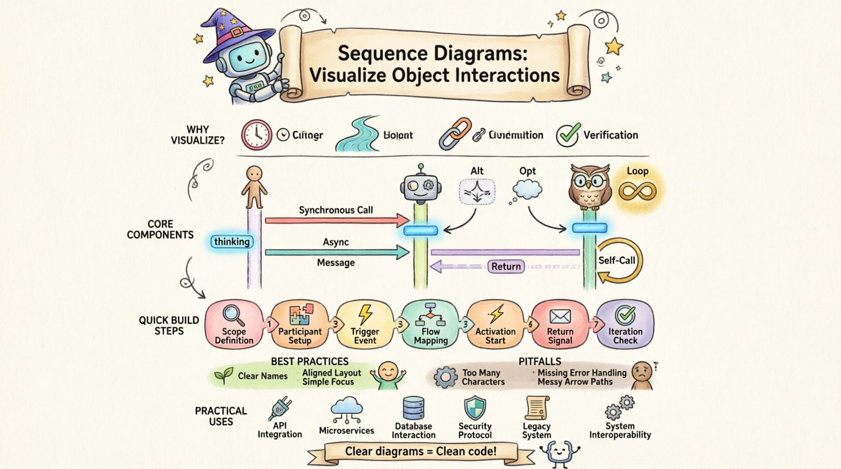
🛠️ Core Components of a Sequence Diagram
To construct an effective diagram, one must understand the standard notation used to represent elements. While specific tools may vary, the underlying semantics remain consistent across Object-Oriented design methodologies.
1. Participants (Lifelines)
Participants represent the objects or actors involved in the interaction. They are typically drawn as rectangles at the top of the diagram, with a dashed vertical line extending downwards. This line is known as the lifeline.
- Actors: External entities, such as a human user or a third-party system, represented by stick figures or labeled boxes.
- Objects: Instances of classes within the system. They are labeled with the class name and instance name (e.g., controller:UserManager).
- Boundary Objects: Interfaces through which users interact with the system.
- Control Objects: Logic that coordinates the flow of the interaction.
- Entity Objects: Data models that store information.
2. Messages
Messages represent the communication between participants. They are drawn as horizontal arrows pointing from the sender’s lifeline to the receiver’s lifeline. The timing is implied by the vertical position on the diagram.
| Type | Arrow Style | Behavior |
|---|---|---|
| Synchronous Message | Filled Arrowhead | Caller waits for response before continuing. |
| Asynchronous Message | Open Arrowhead | Caller sends and continues without waiting. |
| Return Message | Dashed Line | Response sent back to the caller. |
| Self-Message | Circular Arrow | Object invokes a method on itself. |
3. Activation Bars
Also known as execution occurrences, these are thin rectangles drawn on the lifeline. They indicate the period during which an object is performing an action or waiting for a response. A long activation bar suggests a complex operation, while a short one indicates a quick method call.
4. Frames and Combined Fragments
Complex logic often requires conditional branches or loops. Frames allow grouping these behaviors.
- Alt (Alternative): Represents if-else logic. Only one path is executed.
- Opt (Optimal): Represents optional behavior (if condition is met).
- Loop: Represents repeated execution of a message sequence.
- Break: Represents an early exit from a loop.
📝 Step-by-Step Construction Guide
Creating a sequence diagram is a systematic process. It begins with high-level requirements and drills down into specific method calls. Follow these steps to ensure accuracy and utility.
- Define the Scope: Determine the specific use case or scenario being modeled. Do not attempt to diagram the entire system in one view.
- Identify Participants: List all objects and actors required to fulfill the scenario. Include external systems if necessary.
- Establish the Trigger: Determine what initiates the interaction. This is usually the first message from an actor or an event.
- Map the Flow: Draw the messages sequentially from top to bottom. Ensure the sender and receiver are clear.
- Add Activation: Place activation bars where objects are actively processing data.
- Handle Returns: Explicitly draw return messages if they carry significant data or if the flow is asynchronous.
- Review for Cycles: Check for infinite loops or circular dependencies that might cause runtime errors.
🎨 Best Practices for Readability
A diagram that is too dense is useless. The goal is communication, not just documentation. Adhere to these principles to maintain clarity.
- Consistent Naming: Use clear, descriptive names for messages. Avoid generic terms like Process or Get.
- Vertical Alignment: Align participants logically. Group related objects together to minimize crossing lines.
- Limit Complexity: If a diagram exceeds one page, split it into multiple scenarios. Consider using include or extend fragments to reference sub-diagrams.
- Focus on Logic: Do not clutter the diagram with UI details. Focus on the object logic and data flow.
- Use Layers: Separate the presentation layer from the business logic layer to clarify responsibility boundaries.
⚠️ Common Pitfalls to Avoid
Even experienced designers can fall into traps that reduce the value of a sequence diagram. Awareness of these common issues helps maintain high standards.
- Too Many Participants: Including every minor object makes the diagram unreadable. Focus on the critical path.
- Ignoring Error Handling: A diagram showing only the happy path is misleading. Include error scenarios and exceptions.
- Missing Return Messages: Forgetting to show return data can obscure how information flows back to the user.
- Overusing Loops: Replacing a loop with a single message is often clearer than drawing the loop multiple times.
- Inconsistent Notation: Mixing different styles of arrows or lifelines confuses the reader. Stick to standard conventions.
🔗 Relationship with Other Diagrams
Sequence diagrams do not exist in isolation. They are part of a cohesive modeling strategy.
Class Diagrams
Class diagrams define the static structure. Sequence diagrams validate that the structure supports the dynamic behavior. If a message is sent to a class that does not have the corresponding method, the design is flawed.
Use Case Diagrams
Use case diagrams identify the goals of the system. A single use case may require multiple sequence diagrams to fully detail the internal interactions required to achieve that goal.
State Machine Diagrams
State diagrams show the lifecycle of an object. Sequence diagrams show the interaction between objects. Together, they provide a complete picture of object behavior.
💡 Advanced Concepts in Interaction Modeling
As systems grow in complexity, basic message passing may not suffice. Advanced modeling techniques address these nuances.
1. Time Constraints
In real-time systems, timing is critical. Annotations can be added to messages to specify deadlines or timeouts. This is vital for embedded systems or financial trading platforms where latency affects functionality.
2. Object Creation and Destruction
Objects are not permanent. Diagrams should indicate when an object is created (instantiation) and when it is destroyed (deletion). This is often represented by specific symbols on the lifeline.
3. Recursion
Sometimes an object invokes a method that eventually calls back to itself. This is shown with a self-loop. It is important to mark the depth of recursion to prevent stack overflow scenarios.
🛡️ Maintaining the Diagram
A diagram is a living document. As requirements change, the diagram must evolve. Neglecting this maintenance leads to technical debt.
- Version Control: Treat diagrams as code. Store them in version control systems to track changes over time.
- Sync with Code: Ensure the implementation matches the design. If the code changes, update the diagram.
- Review Cycles: Include diagram reviews in the design phase of the development lifecycle.
- Automated Validation: Where possible, use tools that can validate the consistency between class structures and interaction flows.
🚀 Practical Application Scenarios
Understanding when to apply this modeling technique is just as important as knowing how to draw it.
- API Design: Define request and response flows for external developers.
- Microservices: Visualize calls between distributed services to identify network bottlenecks.
- Database Transactions: Map read and write operations to ensure data integrity.
- Security Protocols: Model authentication and authorization flows to verify access controls.
- Legacy Migration: Document existing systems to understand behavior before refactoring.
📐 Theoretical Underpinnings
The sequence diagram is rooted in the theory of object messaging. In object-oriented programming, objects do not share memory directly; they communicate via messages. This encapsulation principle is visually represented by the arrows between lifelines. The diagram enforces the idea that an object should not know the internal state of another; it should only know how to send a message.
This abstraction layer is crucial for scalability. If the internal implementation of an object changes, the message signature remains the same, and other objects do not need to know about the change. This decoupling is a primary goal of OOAD and is made visible through sequence modeling.
🎯 Conclusion on Design Quality
The quality of a sequence diagram is measured by its ability to communicate intent without ambiguity. It serves as a contract between the design team and the implementation team. When the diagram is clear, the code is cleaner. When the diagram is vague, the code becomes brittle.
Investing time in creating robust interaction models pays dividends during the testing and maintenance phases. It reduces the cognitive load on developers and ensures that the system behaves as expected under various conditions. By adhering to standard notations and focusing on the flow of control, teams can build systems that are not only functional but also maintainable and extensible.