Introduction
In the fast-paced world of modern software development, the gap between high-level architectural vision and day-to-day agile execution often becomes a source of friction. Traditional UML modeling can feel disconnected from sprint backlogs, while agile user stories sometimes lack the structural rigor needed for complex system design. Teams frequently struggle with maintaining a “single source of truth,” leading to documentation drift, misaligned expectations, and inefficient retrospectives.
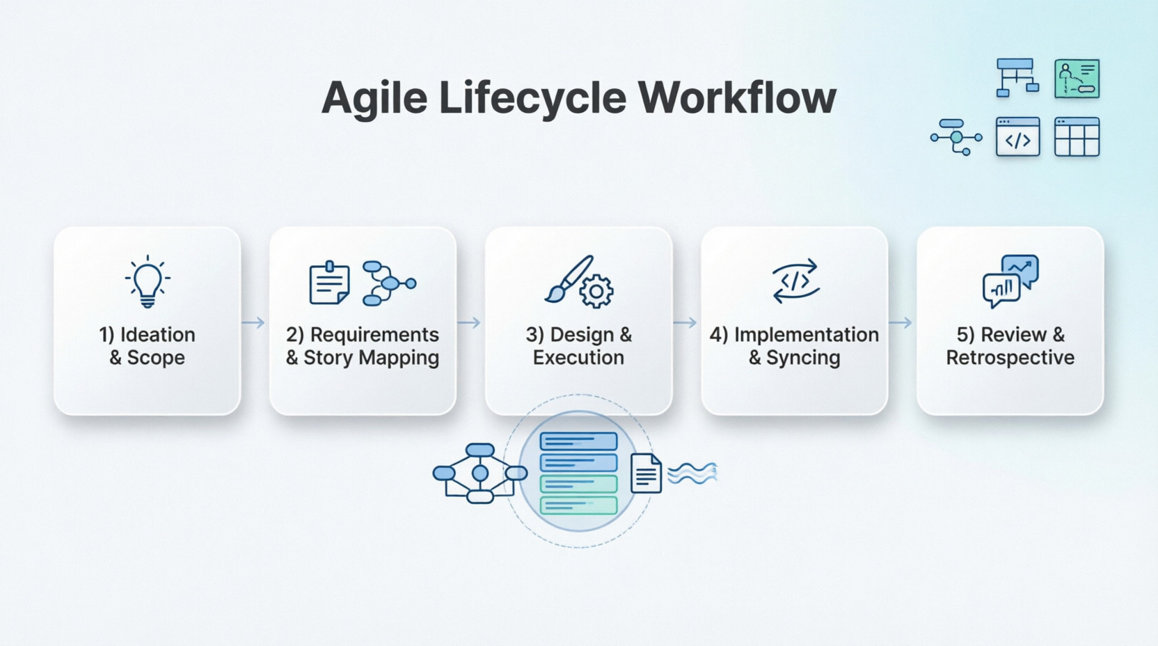
Visual Paradigm addresses this challenge by providing a unified environment that transforms traditional UML Modeling into a collaborative, AI-enabled Agile workflow. By connecting Use Case diagrams directly to user stories, sprint backlogs, and real-time documentation engines, teams can maintain continuity from early ideation through the final retrospective. This case study explores how to structure an end-to-end Agile lifecycle in Visual Paradigm using Use Case Modeling, User Story Maps, OpenDocs, and the Pipeline, ensuring that every artifact remains synchronized and valuable throughout the project lifespan.

Figure 1: Visual Paradigm’s unified interface integrating Agile tools and UML modeling.
1. Ideation & High-Level Scope
The foundation of any successful product lies in clearly defined boundaries and goals. In the ideation phase, teams must establish what the system will do and who it will serve.
Brainstorming & Context
Start by mapping the application’s boundaries. Create a UML Use Case Diagram to visually declare system boundaries, external Actors (users or third-party APIs), and primary system goals (Use Cases). This can be done manually for precision or accelerated via the AI Use Case Diagram Generator, which helps kickstart the modeling process based on natural language descriptions.
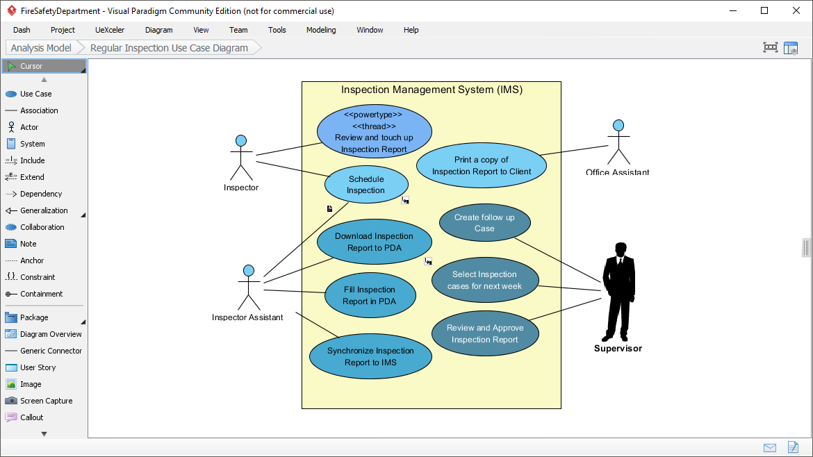
Figure 2: A sample UML Use Case Diagram defining system boundaries and actors.
Kickstarting Documentation
Simultaneously, open OpenDocs, Visual Paradigm’s cloud-based workspace. Here, teams can write down early strategy notes, product visions, or high-level architecture designs. This ensures that textual context is captured alongside visual models from day one.
The Pipeline Bridge
To connect these artifacts, right-click your high-level Use Case diagram in Visual Paradigm Desktop or Online and select Export > Send to OpenDocs Pipeline. In OpenDocs, use Insert > Pipeline to embed the living diagram directly into your vision document. This creates a dynamic link rather than a static image, ensuring that updates to the model reflect immediately in the documentation.
2. Requirements & User Story Mapping
Once the high-level scope is defined, the next step is to break down broad goals into actionable agile requirements.
Breaking Use Cases into Backlog
Visual Paradigm allows a one-to-many relationship between Use Cases and Agile requirements. Take a high-level Use Case (e.g., Book Hotel Room) and transition it seamlessly into an Agile User Story Map. This ensures that every story traces back to a core system function.
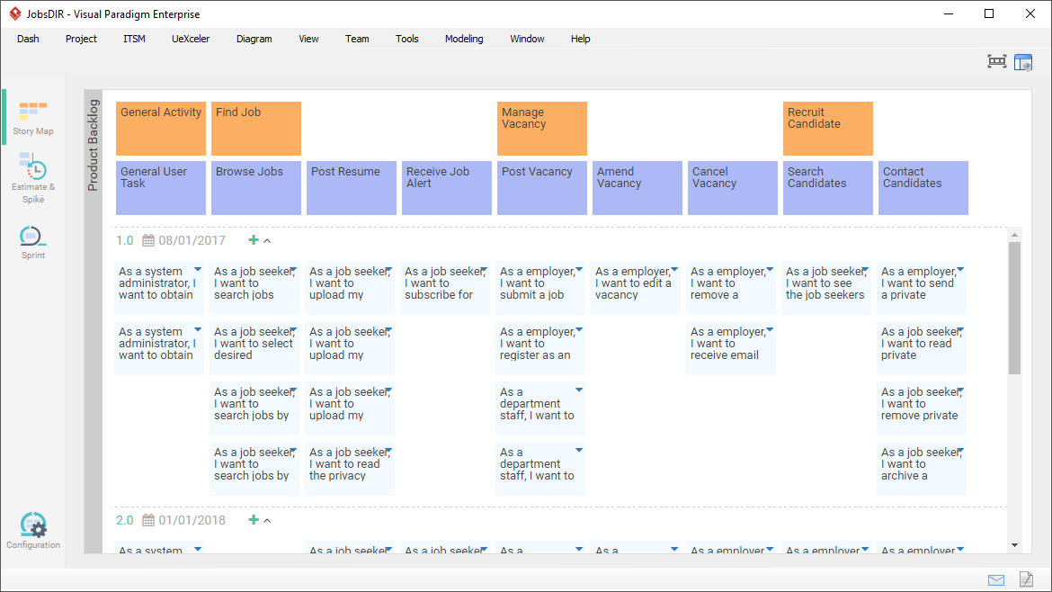
Figure 3: Transitioning from Use Cases to a detailed User Story Map.
Story Mapping Syntax
- Backbone / User Activities: These map directly to your primary Use Cases, forming the horizontal axis of the user journey.
- Epics & User Stories: Break down those activities vertically by releases or priority slices. For example, under Book Hotel Room, you might have Story 1: Browse slots and Story 2: Enter payment.
Detailed Requirements & Testing
Inside the Use Case Details panel, define textual flows of events, alternative paths, and automated acceptance criteria. This acts as a validation gap analysis—if a User Story doesn’t map back to a Use Case, it might be out of scope. Conversely, if a Use Case has no corresponding stories, it may not be prioritized for the current release.
3. Design & Execution (The Blueprint)
With requirements mapped, the team moves into detailed design and sprint execution.
Behavioral Modeling
Developers and architects can automatically generate complex behavioral diagrams from your written Use Case text flows. Generate Sequence Diagrams to detail object interactions, or Activity Diagrams to model logical branching and data workflows. This automation reduces manual effort and ensures consistency between textual requirements and visual designs.
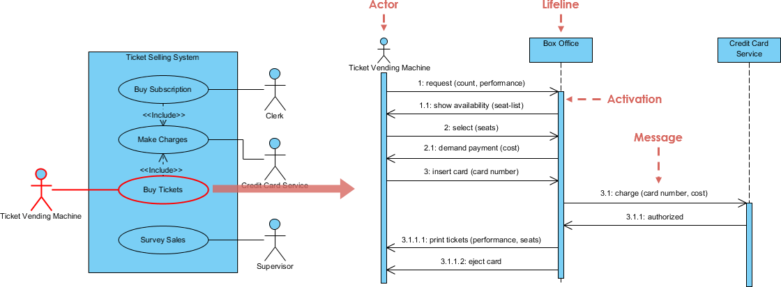
Figure 4: A Sequence Diagram automatically generated from Use Case flow details.
Execution with Scrum Process Canvas
Activate the Scrum Process Canvas, which acts as your Agile workbench. Discuss your user stories using the built-in Affinity Estimation Table, dragging cards into current Sprints. This visual approach facilitates collaboration and consensus during planning sessions.
Task Dispatching
Map implementation items to tasks using Tasifier, the integrated task management tool. You can assign start/due dates, link specific design diagrams, and monitor progress using automated Kanban Boards and Gantt Charts. This keeps the technical execution aligned with the product roadmap.

Figure 5: The Scrum Process Canvas integrating estimation, sprint planning, and task tracking.
4. Implementation, Syncing & Published Results
As development progresses, maintaining alignment between code, models, and documentation is critical.
VPasCode Modeling Alignment
As developers write code, use VPasCode to bridge the gap between structural models (like Class Diagrams) and the active codebase. This feature helps eliminate architectural drift by ensuring that the model reflects the actual implementation and vice versa.
Living Project Synchronization
When code changes force a layout adjustment in your diagrams, modify the source model in your desktop tool. Right-click and re-send it to the OpenDocs Pipeline. This ensures that the documentation always reflects the current state of the system.
No Document Breakage
OpenDocs flags that a new version is available. Click Pipeline in the editor toolbar, view the visual revisions side-by-side, and swap to the latest variant with one click. This preserves text styling and formatting seamlessly without requiring manual re-uploading or breaking static image links.
Publishing Reports
Generate formal stakeholders’ packages or system architecture manuals instantly using Doc. Composer or by sharing cloud-based OpenDocs workspaces. This allows for easy distribution of up-to-date information to non-technical stakeholders.
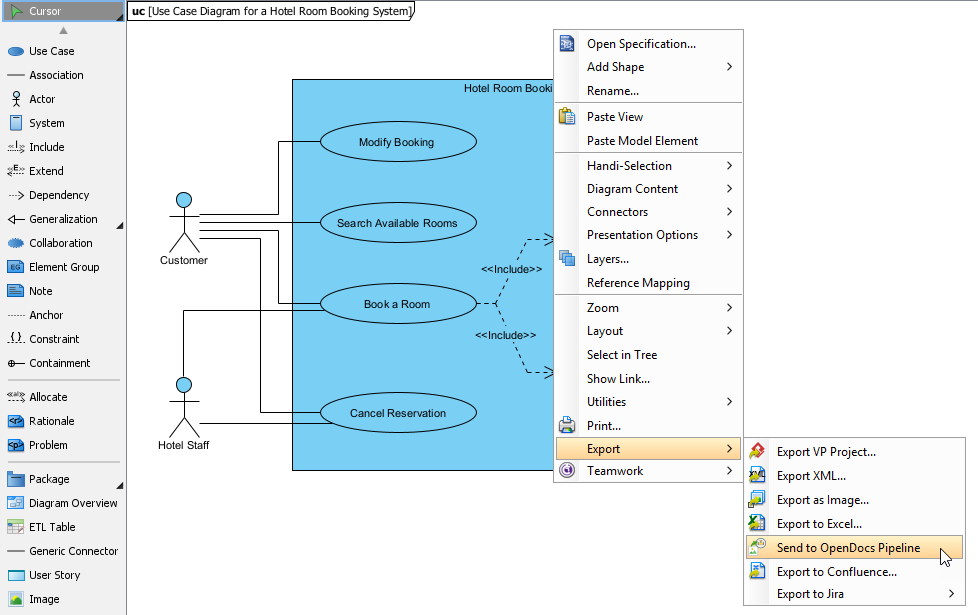
Figure 6: Managing document versions and syncing diagrams via the OpenDocs Pipeline.
5. Sprint Review & Retrospective
The lifecycle concludes with review and reflection, setting the stage for continuous improvement.
Reviewing System Evolution
During the Sprint Review, developers present features side-by-side with the generated sequence or story diagrams to prove alignment with the original architectural scope. This visual evidence helps stakeholders understand how delivered features map back to initial business goals.
Retrospective Workspaces
Utilize the retrospective templates inside the Scrum Process Canvas to Prepare, Conduct, and Analyze the sprint outcomes. Capture team insights, list continuous improvement activities as actionable tasks, and map dependencies back to future story maps or architectural spikes. This closes the loop, ensuring that lessons learned inform the next cycle of ideation and planning.
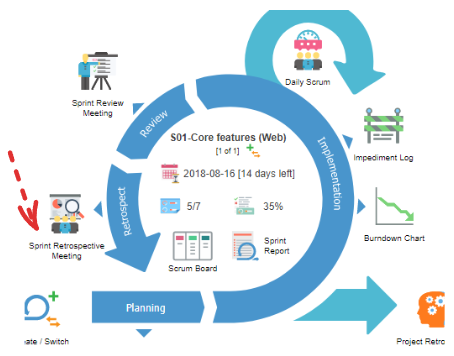
Figure 7: Using retrospective templates to capture insights and plan improvements.
Conclusion
By leveraging Visual Paradigm’s integrated suite of tools, teams can transcend the traditional silos between modeling, agile planning, and documentation. The seamless flow from Use Case diagrams to User Story Maps, through to behavioral designs and live documentation, creates a resilient and transparent development process. This approach not only enhances clarity and alignment but also significantly reduces the overhead associated with maintaining disparate artifacts. As teams adopt this end-to-end workflow, they empower themselves to deliver higher quality software faster, with every stakeholder confident that the final product truly reflects the original vision.