
Mastering Recursive Flows in UML: Sequence Diagrams with Visual Paradigm
In the realm of software architecture and system design, understanding the flow of control and data is paramount. One of the most powerful tools for visualizing this dynamic behavior is the Sequence Diagram. While standard sequence diagrams show linear interactions, complex systems often require a mechanism to represent internal processing loops or recursive calls. This tutorial explores the concept of a Recursive Message, a pattern often seen in database handlers and command execution engines.
Using the industry-standard modeling tool, Visual Paradigm, we will analyze a specific architectural pattern involving a handler, a query command, and a database statement. By the end of this guide, you will understand how to model complex, nested interactions that maintain system clarity.
Understanding the Participants
Before diving into the interaction flow, let’s break down the structural components depicted in the diagram. In Visual Paradigm, these are represented as “Lifelines,” which denote the existence of an object or component over time.
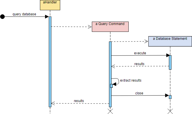
- aHandler (The Controller): Represented by the yellow box, this is the entry point of the system. It acts as the orchestrator, receiving the initial request to “query database.” It is responsible for managing the high-level flow of the operation.
- a Query Command (The Abstraction): Shown in pink, this object represents a specific business logic unit. It acts as an intermediary, translating the handler’s request into a format the database can understand. It creates a “Query Command” context.
- a Database Statement (The Executor): Depicted in blue, this is the lowest level of interaction, typically mapping to SQL execution or a specific database API call. It handles the actual data retrieval and manipulation.
Analyzing the Recursive Message Flow
The core of this diagram is the concept of a Recursive Message. In standard messaging, Object A sends a message to Object B. However, in this architectural pattern, we see a recursive or nested execution flow where the context is passed down, and results are propagated back up.
Step 1: The Entry Point
The process begins with an external trigger (the black circle) sending a query database message to aHandler. The handler activates, indicated by the vertical blue bar (activation bar) on its lifeline.
Step 2: Creating the Command Context
The handler initiates the creation of an a Query Command. In the diagram, this is represented by a dashed arrow with a hollow arrowhead (a “Create” or “Dependency” relationship). This establishes the new scope for the query.
Step 3: The Recursive Execution
Once the query command is active, it must execute the actual data logic. It sends an execute message to a Database Statement. This is where the recursion occurs conceptually: the command delegates the heavy lifting to the statement object. The database statement activates and performs the operation.
Step 4: Result Propagation
The flow reverses as results are returned:
- The a Database Statement sends
resultsback to the a Query Command. - The a Query Command performs local processing, specifically an
extract resultsaction. This is a self-referencing message, shown by the arrow looping back to the activation bar of the command itself. This implies data transformation or parsing logic. - The command closes the statement connection via a
closemessage, ensuring resources are released. - Finally, the a Query Command sends the aggregated
resultsback to the original aHandler.
This structure is crucial for maintaining the Single Responsibility Principle. The handler doesn’t need to know how to connect to the database; it only needs to know how to invoke a command. The command doesn’t need to know the SQL syntax; it only needs to know how to execute a statement.
Visualizing with Visual Paradigm
To replicate this diagram in Visual Paradigm, you would typically use the Sequence Diagram editor. You would define the three classes as Participants, set up their lifelines, and then draw the messages. The “create” relationships are often modeled as dashed lines, while the synchronous messages (solid lines with filled arrows) represent the actual execution flow.
By visualizing this recursive pattern, developers can easily spot bottlenecks. For instance, if the extract results step is too heavy, it becomes obvious that the bottleneck is in the command layer, not the database layer.
Conclusion
Understanding recursive message flows is essential for designing scalable, modular systems. Whether you are building a simple web application or a complex enterprise architecture, the ability to delegate tasks and return results cleanly—exactly as demonstrated in this aHandler example—is a fundamental skill. Visual Paradigm provides the necessary tooling to model these interactions with precision, ensuring that your system architecture is both robust and well-documented.