


A UML State Machine Diagram, also known as a state diagram or statechart, is a powerful modeling tool used to represent the lifecycle and dynamic behavior of a single object or system component. It captures how an object transitions between different states in response to events, enabling a clear visualization of event-driven logic.
✅ Unlike sequence diagrams, which focus on interactions between multiple objects over time, state machine diagrams emphasize the internal state evolution of one entity—making them ideal for modeling complex, reactive systems.
🧩 Core Components of a State Machine Diagram
Understanding these foundational elements is key to building accurate and meaningful state diagrams.
| Element | Description | Visual Representation |
|---|---|---|
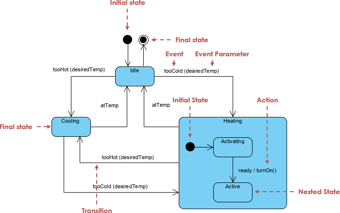
| State | A condition or situation during an object’s lifetime where it satisfies certain constraints, performs actions, or waits for an event. | Rounded rectangle |
| Initial State | Marks the start of the state machine. A filled black circle. | ● |
| Final State | Indicates the end of the process. A concentric circle (black dot inside a circle). | ○● |
| Transition | A directed arrow showing movement from one state to another. | ➔ |
| Event | An incident that triggers a transition. Can be: • Signal Event (e.g., PaymentReceived)• Call Event (e.g., startHeating())• Time Event (e.g., after 5s)• Change Event (e.g., temperature > 80°C) |
event [guard] / action |
| Guard Condition | A Boolean expression that must be true for a transition to occur. | [balance > 0] |
| Action / Entry/Exit |
|
entry / print("Entering Idle") |
| Activity | Ongoing, interruptible behavior performed during a state. | do / run diagnostics() |
| Substate (Composite State) | A state that contains nested states—used to manage complexity. | Nested states within a larger box |
| History State | A pseudo-state that remembers the last active substate before leaving a composite state. Allows resumption. | H (with a circle around it) |
| Fork | Splits a single flow into parallel concurrent flows. | • (filled circle) |
| Join | Merges multiple concurrent flows back into one. | • (filled circle) |
📌 Note: Transitions are often labeled as:
event [guard] / action
Example:PaymentReceived [balance >= 0] / updateBalance()
🛠️ How to Build a State Machine Diagram: Step-by-Step
✅ Step 1: Identify the Object or System
Choose the entity to model (e.g., Toll Booth Controller, Heater System, Voting Ballot).
✅ Step 2: List All Possible States
Define all meaningful conditions the object can be in:
-
Idle -
Vehicle Detected -
Processing Payment -
Payment Received -
Gate Open -
Error / System Failure -
Resetting
✅ Step 3: Define Initial and Final States
-
Start with Initial State (●).
-
End with Final State (○●).
✅ Step 4: Identify Events and Transitions
Ask: What causes the object to change state?
| From State | Event | Guard | To State | Action |
|---|---|---|---|---|
| Idle | Vehicle Detected | — | Vehicle Detected | Start timer |
| Vehicle Detected | Payment Received | balance ≥ 0 | Payment Received | Open gate |
| Vehicle Detected | Timeout | — | Error | Log failure |
✅ Step 5: Add Actions and Activities
Use entry, exit, and do actions:
-
entry / log("Entering Payment State") -
do / validateCard() -
exit / closeGate()
✅ Step 6: Use Substates for Complex Logic
Break down large states into substates:
-
Payment State →
Validating,Processing,Confirmed -
Use history states (
H) to return to the last active substate after interruption.
✅ Step 7: Handle Concurrency with Fork & Join
Use Fork (•) to split into parallel flows:
-
One flow: Process payment
-
Another: Record vehicle data
Merge with Join (•) to resume a single path.
🌍 Real-World Applications & Examples
| System | States | Key Events | Use Case |
|---|---|---|---|
| Automated Toll Booth | Idle → Vehicle Detected → Payment Received → Gate Open → Reset | VehicleDetected, PaymentReceived, Timeout |
Handle vehicles, prevent fraud |
| Heater System | Idle → Heating → Failure | temp < threshold, temp > 90°C, fanFailure |
Safety monitoring |
| Digital Voting Platform | Draft → Submitted → Verified → Counted → Finalized | submitVote(), verifyIdentity(), timeLimitExceeded() |
Secure, auditable voting |
| Auction Process | Open → Bidding → Close → Payment Processing | bidPlaced, auctionEnd, paymentVerified |
Concurrent bid & payment handling |
| MGUK (Formula 1 Kinetic Motor Generator) | Standby → Regenerating → Charging → Reset | energyLevel > 50%, resetSignalReceived |
High-performance energy recovery |
🔍 These diagrams help engineers and designers anticipate edge cases, validate logic, and communicate system behavior clearly across teams.
1. Automated Toll Collection System
This model includes the requested sub-states for plate validation and receipt generation, as well as the penalty and reset flows.
@startuml
[*] --> Idle

Idle --> InRange : Vehicle Detected
state InRange {
  [*] --> PlateValidation
  PlateValidation --> PlateRead : Success
  PlateValidation --> InvalidPlate : Error Handling
}

InRange --> PaymentReceived : Payment Success
state PaymentReceived {
  [*] --> ReceiptGeneration
}

PaymentReceived --> Idle : Lane Cleared
InRange --> NoPayment : Payment Failure
NoPayment --> Penalty : Apply Penalty
Penalty --> Idle : Reset System
@endum
2. Heater System
This example focuses on state-dependent behavior triggered by temperature events (Too Hot/Too Cool) and failure handling.
@startuml
[*] --> Idle

Idle --> Heating : Too Cool
Idle --> Cooling : Too Hot

state Cooling {
  [*] --> Startup
  Startup --> Ready : Fan/Compressor Running
  Ready --> Running
}

Heating --> Idle : OK
Cooling --> Idle : OK

Heating --> Failure : Failure Event
Cooling --> Failure : Failure Event
Failure --> Idle : Failure Cleared [5]
@endum
@startuml
[*] --> Idle
Idle --> Heating : Too Cool
Idle --> Cooling : Too Hot
state Cooling {
[*] --> Startup
Startup --> Ready : Fan/Compressor Running
Ready --> Running
}
Heating --> Idle : OK
Cooling --> Idle : OK
Heating --> Failure : Failure Event
Cooling --> Failure : Failure Event
Failure --> Idle : Failure Cleared
@endum
3. Formula 1 MGUK Module
This model reflects the specific transition logic mentioned in the sources where an error state leads to a reset before returning to idle.
@startuml
[*] --> Ready

Ready --> Error : Fault Detected
Error --> Reset : Initiate Reset
Reset --> Idle : Reset Complete
Ready --> Idle : Standby Command
Idle --> Ready : Activate
@endum
4. Auction Process (Concurrent States)
This diagram uses Fork and Join nodes to show concurrent sub-activities: processing the bid and authorizing the payment limit.
@startuml
[*] --> EnteringAuction

state EnteringAuction {
  state fork_node <<fork>>
  [*] --> fork_node
  fork_node --> ProcessingBid
  fork_node --> AuthorizingPayment

  state join_node <<join>>
  ProcessingBid --> join_node
  AuthorizingPayment --> join_node
  join_node --> [*]
}

EnteringAuction --> Canceled : User Exit
EnteringAuction --> Rejected : Bid/Payment Invalid
EnteringAuction --> Success : Auction Closed
@endum
5. Digital Voting Platform
Based on the intent to capture a voting lifecycle from initiation to final submission.
@startuml
[*] --> Initiation

Initiation --> IdentityVerified : Credential Check
IdentityVerified --> CastingVote : Access Granted
CastingVote --> Reviewing : Selection Made
Reviewing --> Submitted : Confirm Vote
Submitted --> [*] : Process Complete

Reviewing --> CastingVote : Edit Selection
IdentityVerified --> Rejected : Failed Verification
@endum
Why use the AI instead of writing this?
The sources emphasize that writing the code above requires knowledge of specific syntax and manual coding, which has a steeper learning curve. The Visual Paradigm AI simplifies this by allowing you to simply type: “Create a state machine for a toll system with plate validation and penalty states” and having the software instantly render the visual and the underlying logic for you.
🤖 How Visual Paradigm AI Enhances State Machine Modeling
The Visual Paradigm AI Diagram Generator transforms traditional modeling by turning natural language into professional-grade state machine diagrams—fast, accurate, and intelligent.
✨ Key Advantages of AI-Powered State Diagrams
1. Eliminate the “Blank Canvas” Problem
-
No more dragging and aligning elements manually.
-
AI generates a fully laid-out, well-structured diagram from a simple prompt in seconds.
💬 Example Prompt:
“Create a state machine diagram for a toll booth system that detects vehicles, processes payments, and handles errors.”
2. Natural Language Input
-
Describe your system in plain English—no need to learn syntax like PlantUML.
-
AI interprets intent and builds the correct structure.
✅ Prompt:
“Model a heater system that starts heating when temperature drops below 18°C, stops at 22°C, and enters failure if the fan fails.”
→ AI generates:Idle → Heating → Failure, with appropriate events and guards.
3. Conversational Refinement
Engage in a dialogue to refine the model:
-
“Rename ‘Error’ to ‘System Failure'”
-
“Add a reset state between error and idle”
-
“Insert a timeout guard after 10 seconds in ‘Processing Payment’”
🔄 The AI updates the diagram in real time based on feedback.
4. Smart Logic & Best Practices
The AI ensures:
-
Correct UML notation: Triggers, guards, entry/exit actions are properly formatted.
-
Error detection: Flags unreachable states, conflicting transitions, or missing events.
-
Optimal layout: Automatically arranges states for readability and visual clarity.
5. Seamless Integration into Workflow
Once satisfied:
-
Export or import directly into Visual Paradigm Professional Edition.
-
Use for:
-
System design documentation
-
Stakeholder presentations
-
Code generation (via UML models)
-
Model-driven development (MDD)
-
🎯 Best Practices for Effective State Machine Diagrams
| Practice | Why It Matters |
|---|---|
| Keep states atomic and meaningful | Avoid overly complex or vague states like “Something Happened” |
| Use composite states wisely | Break down complex behaviors (e.g., “Payment Processing” → “Validating”, “Transferring”) |
| Always define guards for critical transitions | Prevent unintended state changes (e.g., avoid charging if balance < 0) |
| Minimize unreachable states | Ensure every state is reachable from the initial state |
| Use history states for interrupted processes | Improve usability (e.g., resume voting after timeout) |
| Limit concurrency with Fork/Join | Avoid overcomplicating with too many parallel flows |
📌 Summary: Why Use State Machine Diagrams?
| Benefit | Description |
|---|---|
| Clarity | Visualizes complex behavior in an intuitive way |
| Predictability | Shows how events drive state changes |
| Error Prevention | Reveals edge cases and invalid transitions early |
| Communication | Enables developers, testers, and stakeholders to align on system behavior |
| Foundation for Code | Can be used to generate state machines in code (e.g., in C++, Python, Java) |
📚 Further Reading & Tools
-
UML 2.5 Specification – Official standards for state machines
-
Visual Paradigm – Full-featured UML modeling tool with AI diagram generation
-
PlantUML – Text-based diagramming (for advanced users)
-
Enterprise Architect, StarUML, Lucidchart – Alternative modeling platforms
🏁 Final Thoughts
🔄 A state machine diagram is not just a visual aid—it’s a design contract that defines how your system should behave under various conditions.
With Visual Paradigm’s AI Diagram Generator, creating, refining, and deploying these diagrams has never been easier. Whether you’re modeling a toll system, a voting platform, or a high-performance racing component, you can now turn ideas into accurate, professional diagrams—faster and smarter than ever before.
✅ Start modeling today:
🌐 Try Visual Paradigm AI Diagram Generator
🧠 Describe your system in plain English — get a perfect UML state machine diagram in seconds.
📌 Pro Tip: Save your AI-generated diagrams as templates for future use—accelerate design across similar systems like payment gateways, IoT devices, or workflow engines.
📘 Master the art of state machines. Build smarter systems. Communicate with clarity.
— Your UML State Machine Guide, Powered by AI