In complex software engineering, clarity is the most valuable currency. When systems grow, the cognitive load required to understand interactions between components increases exponentially. This is where the package diagram becomes an essential tool. It serves as a high-level map, allowing architects and developers to visualize the logical grouping of elements within a system. By defining clear boundaries, teams can manage complexity, facilitate parallel development, and ensure long-term maintainability. This guide explores the mechanics, strategies, and principles behind effective package modeling.
🧱 Defining System Boundaries
A system boundary represents the demarcation between different functional areas or logical concerns. In a package diagram, these boundaries are visualized through containers known as packages. These packages act as namespaces or folders that group related classes, interfaces, and components together. The primary goal is to create a structure where internal connections are dense, but external dependencies are minimized.
- Logical Grouping: Packages should reflect a specific responsibility or domain, such as Authentication, Data Access, or Business Logic.
- Encapsulation: Details of the internal implementation remain hidden from other packages. Only defined interfaces are exposed.
- Scalability: Well-defined boundaries allow new features to be added without disrupting existing functionality.
When boundaries are blurred, the system becomes a monolithic blob. Changes in one area ripple unpredictably across the entire architecture. Conversely, sharp boundaries isolate changes, making the system more resilient. Visualizing these boundaries early in the design phase prevents technical debt from accumulating.
📐 Core Elements and Notation
To create an effective diagram, one must understand the standard elements used to represent structure. While specific tools vary, the underlying concepts remain consistent across modeling standards.
1. Packages
Packages are the primary building blocks. They are typically drawn as a folder icon or a rectangle with a tab. The name should be unique within the model and descriptive of the content it holds.
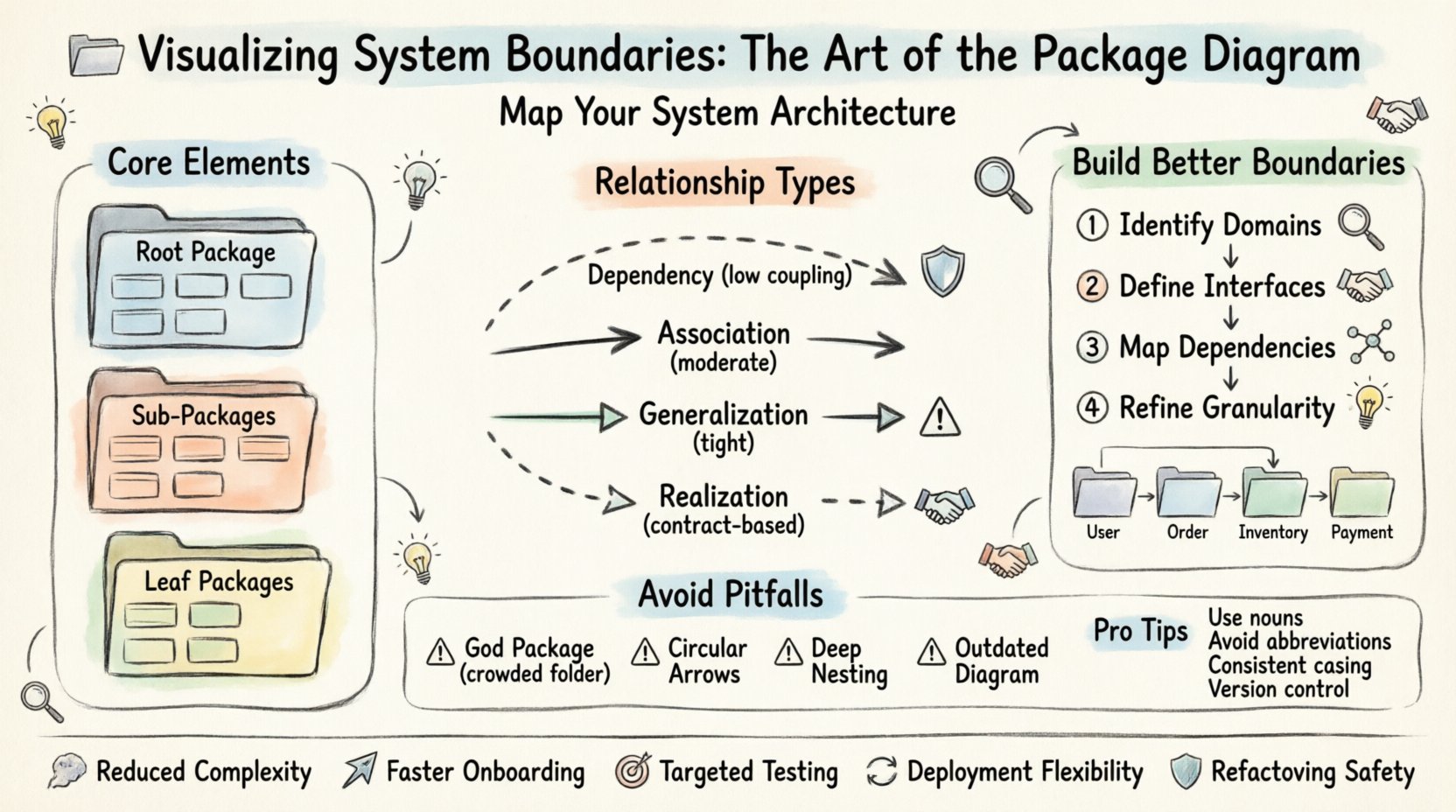
- Root Package: Represents the entire system or application.
- Sub-Packages: Nested packages allow for further organization and hierarchy.
- Leaf Packages: Packages that contain actual classes or interfaces.
2. Classes and Interfaces
While package diagrams focus on the macro view, they often imply the existence of detailed elements inside. A package may contain:
- Classes: Concrete implementations of behavior.
- Interfaces: Contracts that define behavior without implementation.
- Components: Deployable units of software.
3. Relationships
Connections between packages indicate how they interact. These lines describe the flow of information or dependency. Understanding the type of relationship is critical for assessing coupling.
🔗 Understanding Relationships
Dependencies are the lifeblood of a package diagram. They show which packages rely on others to function. Managing these relationships is the core challenge of architectural design. Below is a breakdown of common relationship types.
| Relationship Type | Notation | Meaning | Impact |
|---|---|---|---|
| Dependency | Dashed Arrow | One package uses another. | Low coupling; safe to change if interface is stable. |
| Association | Solid Line | Structural connection between elements. | Moderate coupling; implies knowledge of structure. |
| Generalization | Solid Triangle | Inheritance or realization. | Tight coupling; changes affect both parent and child. |
| Realization | Dashed Triangle | Interface implementation. | Contract-based; allows swapping implementations. |
When drawing these relationships, keep the following in mind:
- Directionality: Arrows should point from the client (dependent) to the supplier (dependent upon).
- Minimalism: If a package does not need to know about another, do not draw a line.
- Abstraction: Use interfaces to reduce the visibility of concrete dependencies.
🛠️ Constructing Effective Diagrams
Building a package diagram is not a one-time task. It is an iterative process that evolves as the system grows. The following steps outline a logical approach to creating a robust architecture.
Step 1: Identify Core Domains
Start by listing the major functional areas of the application. These are the high-level packages. Ask questions like: What are the distinct business capabilities? Where does data originate? How are users authenticated? Grouping these capabilities forms the root structure.
Step 2: Define Interfaces
Before implementing logic, define the contracts. What data does one package need to pass to another? What operations are required? This step ensures that packages communicate via stable boundaries rather than fragile implementation details.
Step 3: Map Dependencies
Draw the arrows. Be honest about what depends on what. If a utility package is used by the entire system, it will have many incoming arrows. If a domain package depends on a database package, draw that link. Avoid circular dependencies, as they create logic loops that are difficult to resolve.
Step 4: Refine Granularity
If a package becomes too crowded, split it. If a package is empty, merge it. The goal is a balance where each package has a single, clear responsibility. This is often referred to as the Single Responsibility Principle applied to architecture.
🏷️ Strategic Naming Conventions
Names are the first thing a reader sees. Poor naming leads to confusion and misinterpretation. A well-named package tells the reader exactly what it contains without needing to open it.
- Use Nouns: Package names should be nouns (e.g., Users, Orders), not verbs (e.g., ProcessOrders).
- Avoid Abbreviations: Unless industry standard, spell out terms. DB is better than DBS, but Database is clearer.
- Consistent Prefixes: Use prefixes for specific contexts, such as UI, Core, or API, to distinguish layers.
- Case Sensitivity: Stick to a specific casing style, such as PascalCase or camelCase, to maintain visual consistency.
Consider the hierarchy. A package named System.Core.Security.Authentication is clear but deep. A flat structure like Auth and Security might be easier to navigate. Choose the depth that matches the team’s mental model.
🚫 Common Pitfalls and Anti-Patterns
Even experienced designers fall into traps. Recognizing these patterns early can save weeks of refactoring.
1. The God Package
A package that contains everything is a failure of design. If you find a package with hundreds of classes, it lacks cohesion. Split it into smaller, focused groups based on their function.
2. Excessive Coupling
When Package A depends on Package B, and Package B depends on Package A, you have a circular dependency. This makes testing and deployment difficult. Break the cycle by introducing an interface or an intermediary package.
3. Over-Nesting
Creating too many layers of sub-packages creates navigation fatigue. A depth of more than three or four levels is often unnecessary. Flatten the structure where possible.
4. Ignoring the Code
A diagram that does not match the code is worse than no diagram. If the code moves but the diagram stays static, it becomes misleading. Ensure the modeling process is integrated into the development workflow.
🔄 Maintaining Diagram Integrity over Time
Software is dynamic. Requirements change, features are added, and legacy code is removed. A static diagram will rot. To keep the package diagram useful, it must be treated as a living document.
- Version Control: Store diagram files alongside the source code. This ensures that changes to the model are tracked.
- Automation: Where possible, generate diagrams from the code. This ensures the visual representation always matches the implementation.
- Regular Reviews: During architectural reviews, inspect the package structure. Ask if the current boundaries still reflect the business needs.
- Documentation: Add notes to the diagram explaining *why* certain boundaries exist. Context is as important as structure.
🌐 Integration with Team Structure
Package diagrams are not just technical artifacts; they are communication tools. They often mirror the organizational structure of the teams working on the software. This concept, known as Conway’s Law, suggests that systems reflect the communication structures of their organizations.
- Team Boundaries: Align package boundaries with team responsibilities. This reduces coordination overhead.
- Ownership: Assign ownership of specific packages to specific teams. This clarifies who is responsible for changes.
- Interface Contracts: Teams should agree on the interfaces between their packages. This allows them to work independently.
📊 Benefits of Clear Boundaries
Investing time in visualizing system boundaries yields significant returns. The advantages extend beyond the diagram itself.
- Reduced Complexity: Developers only need to understand their own package and the interfaces they consume.
- Faster Onboarding: New team members can navigate the system structure quickly using the diagram.
- Targeted Testing: Unit tests can be scoped to specific packages, ensuring isolation.
- Deployment Flexibility: Independent packages can be deployed or scaled separately if the architecture supports it.
- Refactoring Safety: Changes are contained, reducing the risk of breaking unrelated features.
📝 Practical Example Scenario
Imagine an e-commerce platform. A poorly designed system might have a single package containing everything from user login to inventory management to payment processing. A well-designed system would separate these concerns.
- User Package: Handles authentication, profiles, and permissions.
- Order Package: Manages order creation, status, and history.
- Inventory Package: Tracks stock levels and availability.
- Payment Package: Processes transactions and handles receipts.
These packages would interact through defined interfaces. The Order package might request stock from the Inventory package, but it should not know how the Inventory package calculates stock. This separation allows the Inventory team to change their logic without affecting the Order team.
🛡️ Security Implications
Package boundaries also play a role in security. By isolating sensitive logic, you reduce the attack surface.
- Data Isolation: Sensitive data packages should have strict access controls.
- Authentication: Security logic should be centralized in a dedicated package to ensure consistency.
- Dependency Management: Limit which packages can access external libraries to prevent vulnerabilities.
🎯 Final Thoughts on Architecture
Creating a package diagram is an exercise in abstraction. It requires stepping back from the code to see the forest. It is a balance between simplicity and completeness. Too simple, and it lacks detail. Too complex, and it becomes unreadable.
The true value lies in the conversation it generates. When stakeholders review the diagram, they discuss the boundaries, the dependencies, and the responsibilities. This shared understanding is the foundation of a stable, scalable system. As the system evolves, the diagram should evolve with it. Treat it as a map that guides the journey, not a wall that confines it.
Focus on the relationships. Minimize the coupling. Maximize the cohesion. By adhering to these principles, you create a system that is not only functional today but adaptable for tomorrow.