Introduction
In today’s rapidly evolving software development landscape, Unified Modeling Language (UML) has emerged as the industry-standard methodology for visualizing, specifying, constructing, and documenting software systems. However, possessing knowledge of UML notation alone is insufficient—developers and architects need powerful, comprehensive modeling tools that can transform theoretical diagrams into actionable blueprints for enterprise-scale projects.
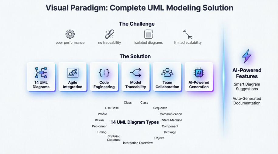
While numerous diagramming tools exist in the market, many fall short when faced with the complexity and dynamic nature of modern software development. Simple drawing tools lack the intelligence to maintain model consistency, traceability, and integration with development workflows. This is where Visual Paradigm distinguishes itself as more than just a diagramming tool—it’s a complete visual modeling ecosystem designed to support the entire software development lifecycle, from requirements gathering to code generation and team collaboration.
This comprehensive guide explores how Visual Paradigm addresses the limitations of conventional diagramming tools while providing enterprise-grade features that scale with your organization’s needs.
The Challenges with Conventional Diagramming Tools
Before diving into solutions, it’s essential to understand the pain points that development teams face with traditional tools:
Performance and Scalability Issues
Web or cloud-based diagrammers may appear attractive with their zero-configuration setup, but they often struggle with performance and lack enterprise-scale capabilities when modeling complex diagrams.
Limited Model Reusability
In many tools, once a model element (such as a class) is created in one diagram, it cannot be referenced elsewhere as a view or shared across different projects. This isolation makes them unsuitable for enterprise-scale modeling where consistency and reusability are paramount.
Lack of Traceability
All diagrams become separate pieces of work without any traceability among them, making it difficult to maintain consistency and understand relationships between different aspects of the system.
Insufficient Development Support
Most diagramming tools lack the robust toolset needed to unleash UML’s full potential across various software development activities, including teamwork, agile development, UX modeling, code engineering, and enterprise project management.
Drawing vs. Modeling
Tools like Visio are suitable only for drawing simple diagrams and lack sophisticated editing features for complex diagram layout and modification. What you end up with is a set of standalone diagrams that aren’t powerful enough to scale with the entire software development process.
Visual Paradigm: The Comprehensive Solution
Visual Paradigm addresses these challenges head-on with a feature-rich platform that goes far beyond simple diagramming.
Excellent Visual Modeling Toolset
Unlike other UML tools with limited notation support, Visual Paradigm supports the latest UML 2.x standard with all 14 different types of diagrams, plus related visual modeling standards such as:
-
BPMN (Business Process Model and Notation)
-
Mind maps
-
Textual Analysis
-
Project Management tools (ArchiMate, Fishbone, PERT, Gantt, WBS, Radar Chart, and many more)
Agile and Scrum Integration
Visual Paradigm seamlessly integrates use case modeling with agile development practices:
-
Story Map Integration: Connect use cases with story maps for effective backlog management and release planning
-
Multi-Source Requirements: Send various visual models to agile product backlogs, including requirements from use cases, activities from UML Activity Diagrams, tasks from BPMN, or nodes from mind maps
-
Requirement Breakdown: Transform large requirements like use cases into manageable user stories or epics, organized in a structured story map
-
Task Management: Once use cases are transformed into user stories, they can be broken down into tasks and managed automatically
Code Engineering Capabilities
Bridge the gap between design and implementation:
-
Code Generation: Generate code from class and state diagrams for popular programming languages
-
Database Engineering: Generate databases from ERDs and map them to class diagrams using the Hibernate framework (supporting major databases)
-
IDE Integration: Seamless integration with leading IDEs including Visual Studio, IntelliJ, NetBeans, Eclipse, and Android Studio
Inter-Model Traceability
Maintain consistency across your entire project:
-
Model References: Support for one model with multiple views across different diagrams
-
Cross-Project References: Reference visual models across multiple projects
-
Automated Diagram Generation: Generate sequence diagrams or activity diagrams from use case scenarios
-
Wireframe Integration: Elaborate use case scenarios with wireframe tools
-
Model Transitor: Identify classes from sequence diagrams and relate models to one another
On-Demand Report Designer
Communicate your designs effectively:
-
Drag & Drop Reporting: Simply drag model elements or diagrams to compose custom reports
-
Multiple Output Formats: Export to Word, PDF, or HTML
-
Documentation Composer: Embed model elements or diagrams directly into corporate reports and documents
Team Collaboration
Work together seamlessly:
-
Concurrent Editing: Team members can edit UML projects simultaneously with automatic version control
-
Conflict Resolution: Automatic modification merge and conflict resolution
-
Cloud Collaboration: Share, discuss, and comment on diagrams online through the PostMania feature
-
File Cabinet: Attach and classify references and documents in a visual, organized manner
Web Diagrams and Online Resources
Access diagrams from anywhere:
-
Web Diagrams Online: Create BPMN, business process diagrams, ArchiMate, class diagrams, use case diagrams, sequence diagrams, flowcharts, PERT, ITIL, AWS, and Microsoft Azure diagrams online
-
No Additional Cost: Existing Visual Paradigm users can access web diagrams at no extra charge
-
Sample Diagrams: Import sample diagrams from the Visual Paradigm Community Circle for learning, experimentation, or as templates
Comprehensive UML Diagram Support
Visual Paradigm supports all 14 UML 2.x diagram types, each designed for specific modeling purposes.
Use Case Diagram
Capture functional requirements with UML use case diagram tool. Each use case in a use case diagram represents a high level business goal that yields a measurable result of business values. (UML) Actors are connected with use cases to represent the roles that interact with the functions.

Class Diagram
The UML modeling tool lets you model the structure of system by modeling its classes, their attributes and operations in a UML class diagram. UML class diagram is a blueprint of the classes (code level) required to build a software system. Programmers implement a software system with the help of both the class diagram and the class specification.

Sequence Diagram
Visualize the interactions between users, systems and sub-systems over time through message passing between objects or roles. If class diagram represents the skeleton of classes by showing their attributes and methods, UML sequence diagram complete the classes by representing the programming logic to be filled in methods’ body.

Communication Diagram
Collaboration between objects in runtime can be modeled in the UML tool, with a UML communication diagram. In a communication diagram, objects, called lifelines, are connected to represent the need of communication during the execution of an interaction. Messages can be added on top of the connectors to list the calls made from and to those lifelines.

Activity Diagram
Use UML activity diagram, a flowchart-based diagram to model the flow of control. Partition actions according to the type of participant involved.

State Machine Diagram
State machine diagram is a critical design model for event-driven systems. Well-designed state machine shows accurately the essential states of objects as well as the triggers of state change, which facilitates the development of error-free state machine.

Component Diagram
Components diagrams are used to model the structure of systems by showing how little parts of the system gear up in forming a bigger part, or forming the entire software systems.

Deployment Diagram
Models the physical deployment of software components with UML deployment diagram. In deployment diagram, hardware components (e.g. web server, mail server, application server) are presented as nodes, with the software components that run inside the hardware components presented as artifacts.

Package Diagram
Arrange and organize model for large-scale project with package diagrams. Package diagram is also good in visualizing structure and dependency between sub-systems or modules.

Object Diagram
View a snapshot of instances of classifiers in UML class diagrams. Similar to class diagrams, object diagrams show the static design of a system from a prototypical perspective.

Composite Structure Diagram
Visualize the internal structure of a class or collaboration with UML composite structure diagram. Model a system from a micro point-of-view using UML composite structure diagram.

Timing Diagram
Timing diagrams model the behavior of objects throughout a given period of time. It is a commonly used UML tool for designing real-time and distributed systems. Just drag to move a time unit back and forth. Have a timing frame updated automatically according to your change.

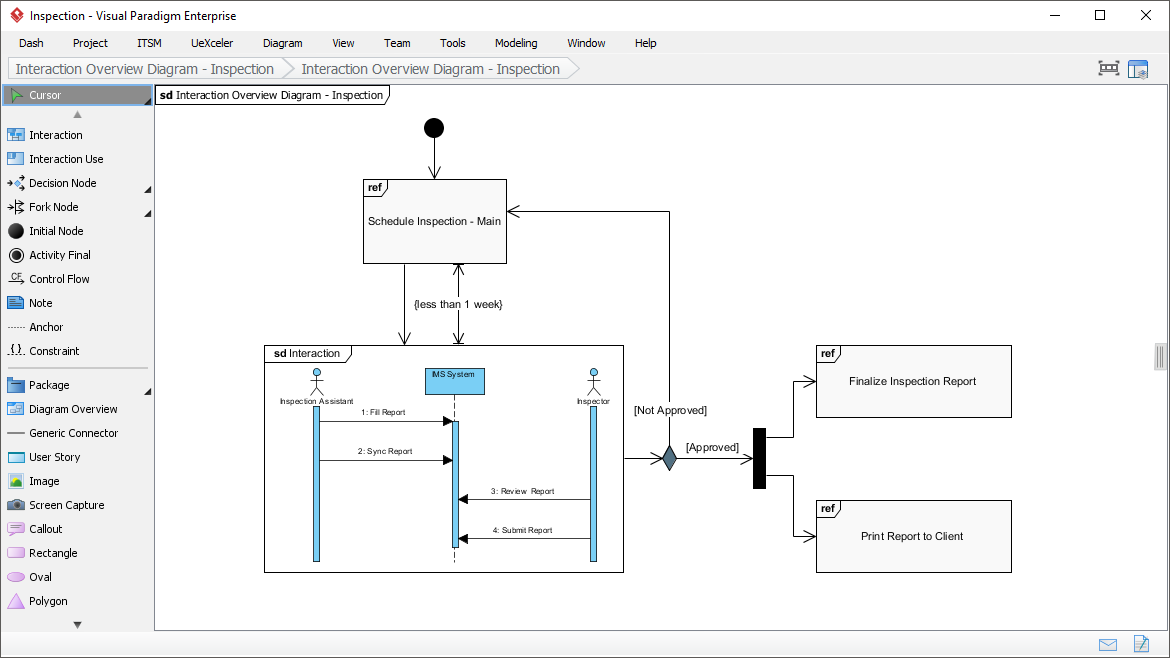
Interaction Overview Diagram
View the sequence of interactions with UML interaction overview diagram. Interaction overview diagram helps represent complex scenario that involve multiple interactions presented as multiple UML sequence diagrams.
Profile Diagram
A visual way to define stereotypes to use in your project. Draw stereotypes, define their tags and their inter-relationships like generalizations and associations. Specify formatting options like background color and icons.

Advanced Modeling Features
Model Element Referencing

Add diagrams, shapes, model elements as internal references
Make internal links between different kinds of project artifacts. Those references work both in Visual Paradigm and in any document and Web contents generated from your design.
Add business documents as external references
Maintain reference between software design and the business documents to help find out why a design decision was made.
Mark in shape body when have reference added
Glance over a design. The tiny marker that appear in shapes’ body indicates that the shapes have references added.
Reference model element in description
Insert model element references to rich text description. The referenced model elements will be linked and highlighted.
Architecture Meets Intelligence: AI-Powered UML Modeling
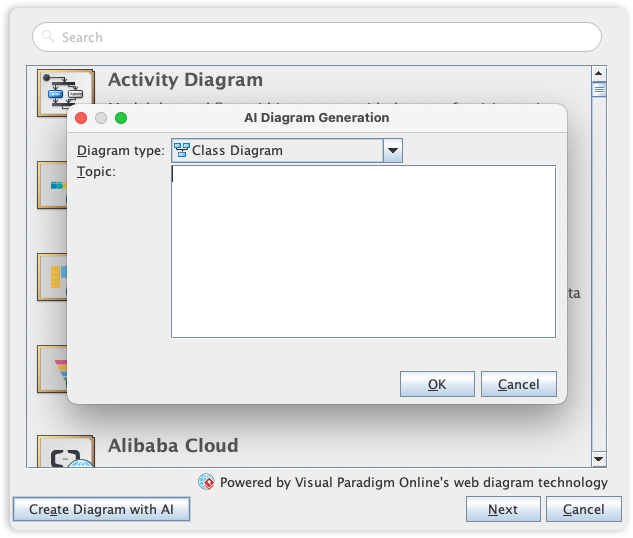
Visual Paradigm’s UML toolset is the industry standard for software modeling, offering the full range of diagrams needed to bridge the gap between requirements and implementation. We are now elevating the entire modeling experience by integrating comprehensive UML support into our AI Diagram Generator, enabling you to visualize system behavior and structure with unprecedented speed.
This capability allows you to instantly generate a wide array of UML diagrams—including Use Case, Class, Sequence, State Machine, Requirement, and Object Diagrams—from a simple textual description. By leveraging AI to interpret your system requirements, the tool automatically maps out the necessary entities, relationships, and interactions, allowing you to move directly to design validation and architectural refinement instead of starting from a blank canvas.
Quick Access Resources

Conclusion
Visual Paradigm represents a paradigm shift from simple diagramming tools to comprehensive visual modeling platforms that support the entire software development lifecycle. By addressing the critical limitations of conventional tools—lack of traceability, poor scalability, isolated diagrams, and insufficient development integration—Visual Paradigm empowers development teams to create, maintain, and evolve complex software systems with confidence.
The platform’s support for all 14 UML 2.x diagrams, combined with agile integration, code engineering capabilities, AI-powered diagram generation, and robust team collaboration features, makes it an indispensable tool for modern software development. Whether you’re working on enterprise-scale projects, adopting agile methodologies, or seeking to bridge the gap between business requirements and technical implementation, Visual Paradigm provides the comprehensive toolset needed to transform visual models into working software systems.
In an era where software complexity continues to grow and development cycles accelerate, having a modeling tool that scales with your needs while maintaining consistency, traceability, and integration is not just beneficial—it’s essential. Visual Paradigm delivers exactly that, making it the go-to solution for professional software modeling and design.
References
- AI-Powered Visual Modeling and Design Solutions: This resource highlights AI-driven tools for visual modeling and diagramming that accelerate software development workflows.
- AI Textual Analysis – Transform Text into Visual Models Automatically: AI identifies system elements from unstructured descriptions to automatically generate UML diagrams, such as class and use case models.
- AI-Powered UML Class Diagram Generator: This tool utilizes AI-assisted automation to generate accurate UML class diagrams directly from natural language input.
- Mastering UML Activity Diagrams with AI: This article explores how AI features enhance the creation and optimization of UML activity diagrams for developers and analysts.
- Visual Paradigm – AI-Powered UML Sequence Diagrams: This resource explains how to generate professional UML sequence diagrams instantly using AI within a modeling suite.
- AI-Powered Use Case to Activity Diagram Tutorial: A step-by-step guide demonstrating how to automatically convert use case descriptions into detailed activity diagrams using AI automation.
- The Future of Modeling: AI and UML Diagram Generation: This analysis discusses how artificial intelligence is transforming UML diagram creation by streamlining complex modeling tasks.
- AI-Powered Component Diagrams with Visual Paradigm Chatbot: This article details how the AI chatbot simplifies component diagram creation by transforming natural language into precise models.
- UML Package Diagram: Structuring Your Codebase with AI: A guide on using AI to aid in structuring systems, managing dependencies, and maintaining scalable software architecture through UML package diagrams.
- How AI Chatbot Can Help You Learn UML Faster: This blog post explains how AI assistants support interactive UML learning by providing real-time feedback and visualizing concepts instantly.