Visualizing how software components interact is a critical step in system architecture. Among the Unified Modeling Language (UML) interaction diagrams, the Communication Diagram stands out for its focus on object relationships rather than strict timeline sequencing. While powerful, creating an effective diagram requires discipline. This guide outlines the essential practices to ensure your models are clear, maintainable, and useful for development teams. We will explore the structural elements, best practices, common errors to avoid, and strategic considerations for implementation.
Understanding the Communication Diagram 🧩
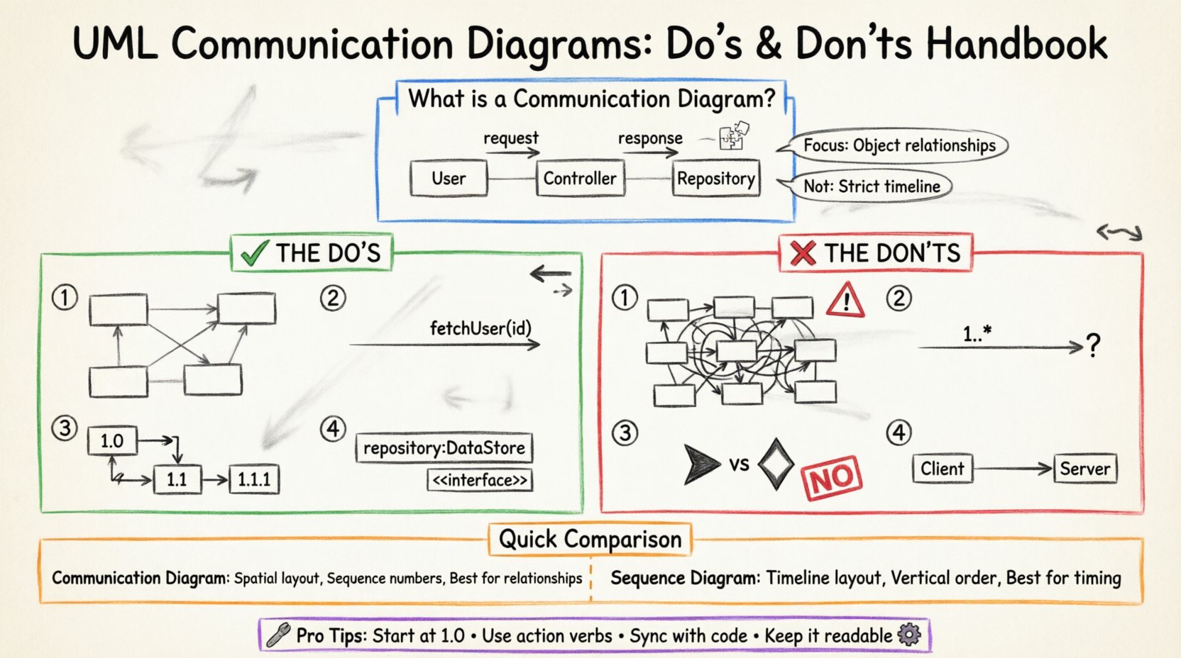
A Communication Diagram, formerly known as a Collaboration Diagram, is a dynamic view within the UML specification. It depicts the interactions between objects or parts of a system in terms of send and receive messages. Unlike the Sequence Diagram, which emphasizes the chronological order of events, the Communication Diagram emphasizes the structural organization of the objects involved. This spatial arrangement allows architects to see how components are linked and how data flows through the network of objects.
These diagrams are particularly valuable during the design phase when the focus is on identifying responsibilities and connections. They help answer questions like, “Which object initiates the request?” and “How does the information travel between the service layer and the data layer?” By adhering to specific guidelines, you ensure that the diagram serves as a reliable blueprint rather than a confusing sketch.
Core Structural Elements 🔨
To build a valid diagram, you must understand the fundamental building blocks. Every diagram is constructed from the following components:
- Objects: Represented by rectangles, these denote instances of classes participating in the interaction. They usually appear with their class name and an instance identifier (e.g., customer:Customer).
- Links: Lines connecting objects that represent associations. These are the pathways through which messages travel. They imply a structural relationship established during the static design phase.
- Messages: Arrows indicating the flow of information. Messages have a source, a target, and a label describing the operation being invoked.
- Sequence Numbers: Small integers placed next to the message label (e.g., 1.0, 1.1, 1.1.1). These indicate the order of execution and nested calls.
- Return Messages: Dashed lines indicating a response or return value. These are often implicit but explicit labeling helps clarify control flow.
The Do’s: Best Practices for Clarity ✅
Creating a high-quality diagram involves making intentional decisions about layout and labeling. Following these principles reduces ambiguity and aids stakeholder understanding.
1. Prioritize Readable Layouts 📐
The arrangement of objects on the canvas should reflect logical relationships, not random placement. Consider the following strategies:
- Group Related Objects: Place objects that interact frequently near each other. This reduces the length of connecting lines and visually groups functional areas.
- Minimize Crossings: Aim for a layout where links and messages do not cross unnecessarily. Overlapping lines create visual noise and make tracing the flow difficult.
- Use White Space: Do not force every object into a tight grid. Adequate spacing allows the eye to rest and helps distinguish between different interaction flows.
- Align Horizontally: When possible, align objects that perform similar roles (e.g., all data access objects) to create a consistent visual pattern.
2. Label Messages Precisely 🏷️
A message label is the primary source of information in the diagram. It tells the reader what happens, not just that something happens.
- Use Action Verbs: Start labels with verbs (e.g., fetchData, validateUser, calculateTotal). This clarifies the intent of the operation.
- Include Parameters: If the message carries significant data, list key parameters (e.g., getUser(id: int)). This prevents ambiguity about what information is required.
- Indicate Return Values: If a message returns a critical object or status, note it in the label (e.g., getReport() → Report).
- Keep Labels Short: Long descriptions clutter the diagram. If an operation is complex, use a note or a separate description block rather than elongating the arrow.
3. Maintain Consistent Sequence Numbering 🔢
Communication diagrams rely on sequence numbers to establish order. Inconsistent numbering leads to confusion regarding execution flow.
- Start at 1.0: Begin the top-level interaction with 1.0.
- Nest Correctly: If object A calls object B, and object B calls object C, the numbering should be 1.0, 1.1, 1.1.1. This hierarchy shows the depth of the call stack.
- Use Sequential Steps: For parallel interactions, use 1.0, 1.1, 1.2 rather than jumping to 5.0. This implies a linear progression in the documentation.
4. Define Object Roles Explicitly 🎭
Objects in the diagram should represent specific roles within the system architecture. This prevents the diagram from becoming a generic list of class names.
- Use Interface Roles: Where possible, label objects by the interface they implement (e.g., repository:DataStore) rather than concrete class names. This allows for implementation changes without altering the diagram.
- Clarify Ownership: Indicate which object is the initiator. This helps identify the entry point for the use case.
The Don’ts: Common Pitfalls to Avoid ❌
Even experienced architects make mistakes that degrade the value of a diagram. Avoid these common errors to maintain the integrity of your documentation.
1. Do Not Overcrowd the Diagram 🚫
A single diagram should cover a specific scenario or a cohesive group of interactions. Trying to map the entire system into one image is a recipe for failure.
- Split by Function: If the interaction involves more than 15 objects, consider splitting the diagram into multiple views (e.g., one for User Login, one for Order Processing).
- Hide Implementation Details: Do not include internal variables or private methods unless they are critical to the external interaction. Focus on the public contract.
- Limit Complexity: If a loop or condition involves too many branches, document the logic in text notes rather than drawing every path.
2. Do Not Ignore Multiplicity 📉
Links represent associations between objects, and these associations often have cardinality constraints. Ignoring this leads to unrealistic models.
- Check One-to-Many: Ensure the diagram reflects if one object can interact with multiple instances of another (e.g., one Customer to many Orders).
- Use Multiplicity Labels: Place multiplicity indicators (e.g., 1, 0..*, 1..*) on the link ends. This documents the structural rules that govern the interaction.
3. Do Not Mix Notation Styles 🎨
Consistency is key for maintainability. Switching between different visual styles within the same document confuses the reader.
- Stick to Standard Arrows: Use solid arrows for synchronous calls and dashed arrows for returns. Do not invent new arrow types.
- Uniform Fonts: Use the same font family and size for object labels and message labels throughout the document.
- Color Usage: If you use color to denote status (e.g., error states), define a legend and apply it consistently. Do not use color arbitrarily.
4. Do Not Omit the Context 🌍
A diagram showing a single message flow without context is often useless. Readers need to know what triggered the interaction.
- Identify the Trigger: Clearly label the initial message that starts the sequence. This is often a user action or an external event.
- Define the Outcome: Indicate the final state or the resulting object returned to the initiator.
- State the Scope: If the diagram represents a specific use case, title it with the use case name (e.g., ProcessPayment).
Communication Diagrams vs. Sequence Diagrams ⚖️
Selecting the right tool for the job is part of the design process. While both are interaction diagrams, they serve different analytical purposes. The following table compares their characteristics.
| Feature | Communication Diagram | Sequence Diagram |
|---|---|---|
| Primary Focus | Object structure and links | Time and order of messages |
| Visual Layout | Network of objects (Spatial) | Vertical timeline (Linear) |
| Message Flow | Requires sequence numbers | Inherent vertical order |
| Best For | Understanding object relationships | Understanding execution timing |
| Complexity | Can get messy with many loops | Handles complex timing well |
Use the Communication Diagram when the team needs to understand how components are wired together. Use the Sequence Diagram when the timing, concurrency, or specific order of operations is the primary concern.
Creating the Model: A Step-by-Step Approach 🛠️
Building the diagram is an iterative process. Follow these steps to ensure a systematic approach to modeling.
- Define the Scenario: Write a brief text description of the use case. What is the goal? What are the inputs and outputs?
- Identify Objects: List the classes or components involved. Remove any that do not participate directly in the interaction.
- Draw the Links: Connect the objects based on your static model. Ensure the links represent valid associations.
- Add Messages: Draw the arrows representing the flow. Start with the initiator and follow the logic.
- Number the Flow: Assign sequence numbers to indicate order. Check for nesting accuracy.
- Review for Clarity: Step back and read the diagram without looking at the text. Can you trace the flow? If not, adjust the labels or layout.
Maintenance and Evolution 🔄
A diagram is not a one-time artifact. It must evolve as the software changes. Treat the Communication Diagram as living documentation.
- Sync with Code: Whenever a method signature changes, update the message label immediately. Outdated diagrams are worse than no diagrams.
- Version Control: Store diagrams alongside the source code. If possible, use tools that allow for version history tracking.
- Refactor for Readability: If a diagram becomes too complex to read, refactor the design or split the diagram. Do not accept technical debt in the documentation.
- Update Context: If the business logic changes the trigger or the outcome, update the diagram title and context notes.
Advanced Considerations for Complex Systems 🧠
For enterprise-level applications, standard diagrams may need to accommodate advanced patterns. Keep these scenarios in mind.
Handling Loops and Conditions
Loops and conditional logic can clutter a diagram. Instead of drawing every iteration, use text notes.
- Use Notes: Add a note box labeled “Loop” or “Condition” pointing to the relevant link.
- Label the Logic: In the note, specify the condition (e.g., While items < 100) rather than drawing the loop arrow repeatedly.
Exception Handling
Errors are part of the system flow. They should be modeled explicitly.
- Differentiate Arrows: Use a distinct style for error messages, such as a red dashed line or a specific label prefix (e.g., throw Error).
- Trace Recovery: Show how the system recovers from the error. Does it retry? Does it notify the user?
Asynchronous Calls
Not all interactions are synchronous. Some messages fire and forget.
- Open Arrowheads: Use an open arrowhead to denote asynchronous messages.
- No Return: Do not draw a return arrow for asynchronous calls unless a callback is explicitly modeled.
Final Thoughts on Documentation Quality 📝
The value of a Communication Diagram lies in its ability to convey complex interactions simply. By adhering to the do’s and avoiding the don’ts, you create a resource that aids both development and maintenance. Remember that the goal is communication, not just compliance with a standard. A diagram that is easy to read is a diagram that is used. Prioritize clarity over completeness, and ensure that the model reflects the current reality of the system.
Regular reviews with the team can help identify areas where the diagram is unclear. Feedback loops are essential for refining the visual language of your project. As the system grows, your documentation should grow with it, maintaining the same standards of precision and structure. This approach ensures that the knowledge remains accessible to new team members and valuable for future refactoring efforts.