UML communication diagrams, historically known as collaboration diagrams, provide a spatial view of how objects interact within a system. Unlike sequence diagrams which focus heavily on time, communication diagrams prioritize the structural relationships between components. Understanding the specific symbols used in this notation is essential for architects and developers who need to document complex object interactions clearly.
This guide breaks down every element found in a standard communication diagram. We will explore the visual syntax, the meaning behind the arrows, and how to represent multiplicity without cluttering the design. By mastering these components, you ensure that your system documentation remains accurate and readable.
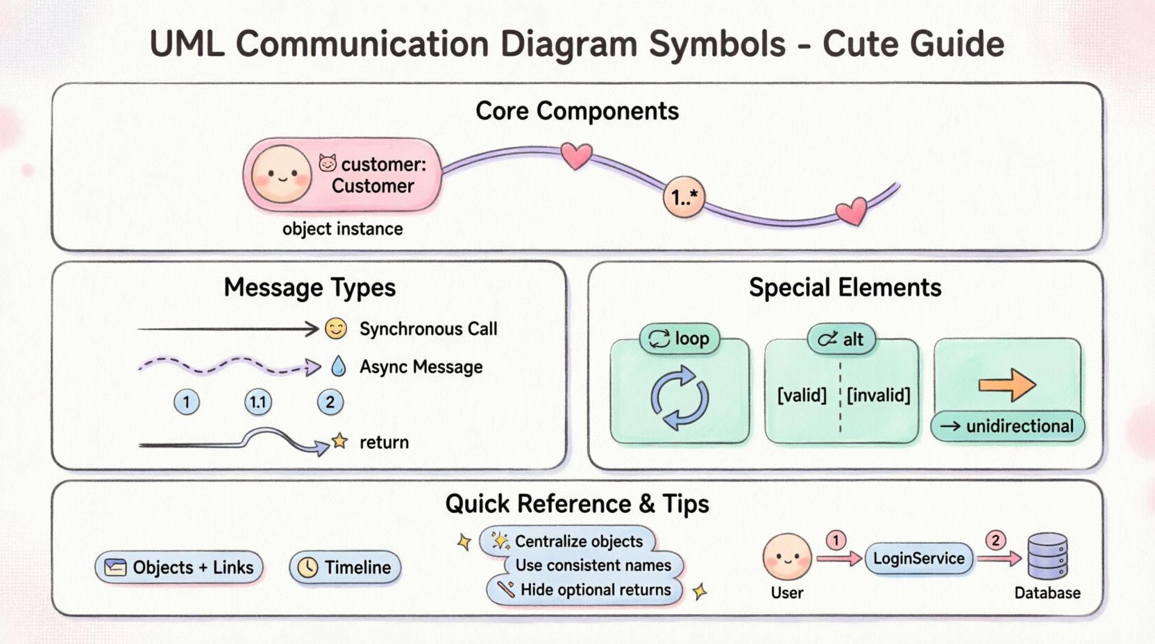
🏗️ Core Components of the Diagram
A communication diagram is essentially a graph of nodes and edges. Each node represents a part of the system, and each edge represents a connection or interaction. The following sections detail the specific symbols used to construct these graphs.
1. Object Instances (Nodes)
The most fundamental building block is the object. In a communication diagram, objects represent instances of classes that participate in the interaction. They are depicted as rectangles with the following characteristics:
- Shape: A simple rectangle.
- Labeling: The text inside the rectangle typically shows the instance name followed by a colon and the class name (e.g., customer: Customer).
- Formatting: The instance name is often underlined to distinguish it from the class name.
- Multiplicity: Sometimes, if an object represents a collection, the multiplicity is shown near the object label.
These nodes act as the endpoints for all messages. Without objects, there is no context for the communication. When drawing these, ensure the names are unique within the scope of the diagram to avoid ambiguity.
2. Links (Associations)
Links connect the object instances. They represent the associations defined in the class diagram. These lines indicate that one object holds a reference to another, allowing messages to be sent.
- Visual: A solid straight line connecting two object rectangles.
- Directionality: By default, links are bidirectional. However, specific navigability can be indicated by an arrowhead on the line.
- Role Names: Text placed near the link describes the role the connected object plays (e.g., manager, client).
It is important to note that links do not change during the execution of the scenario. They represent the static structure that enables the dynamic behavior shown by the messages.
| Symbol | Visual Representation | Meaning |
|---|---|---|
| Object | Rectangle with text | An instance of a class participating in the interaction |
| Link | Solid line | A structural connection allowing communication |
| Navigation Arrow | Open arrowhead on line | Indicates the direction of association traversal |
| Multiplicity | Numbers like 1..*, 0..1 | Defines how many instances can be connected |
📩 Message Symbols and Flow
Messages are the heart of the communication diagram. They show the flow of control and data between objects. Unlike sequence diagrams, these are not arranged on a vertical timeline. Instead, they are placed along the links connecting the objects.
3. Message Arrows
A message is represented by an arrow connecting two objects. The arrow points from the sender to the receiver. The arrowhead style indicates the type of communication:
- Solid Arrowhead: Represents a synchronous call. The sender waits for the receiver to complete the operation before continuing.
- Dashed Arrowhead: Represents an asynchronous message. The sender sends the message and continues immediately without waiting.
- Filled Arrowhead: Sometimes used to indicate a return message, though return messages are often omitted for clarity.
The label on the arrow contains the name of the operation or method being called. Parameters may be included in parentheses. For example, calculateTotal(price, tax).
4. Sequence Numbers
Because the diagram is not time-sorted vertically, sequence numbers are critical. They tell the reader the order in which messages occur.
- Format: A number followed by a dot (e.g., 1, 1.1, 2).
- Root Messages: Start at 1.
- Recursive Messages: If a message triggers another message that is nested within the first call, use decimal numbers like 1.1, 1.2.
- Parallel Messages: Messages that happen at the same time but are not nested might be numbered sequentially (e.g., 2, 3).
These numbers allow the reader to reconstruct the timeline of the interaction. They are placed near the message arrow, usually at the start or end of the arrow line.
5. Return Messages
Return messages indicate that a result is sent back to the caller. In communication diagrams, these are optional. If included, they are often shown as dashed arrows pointing back to the sender. They are typically unlabeled unless a specific return value is significant. Omitting them keeps the diagram cleaner, as the flow of control is implied by the sequence numbers.
🔢 Multiplicity and Constraints
Communication diagrams often deal with collections of objects. Multiplicity symbols indicate how many instances of a class are involved in the link.
- Single Instance: No symbol or 1.
- Many Instances: An asterisk * or 0..* indicates zero or more.
- Specific Range: 2..5 indicates a specific count range.
- Placement: Multiplicity is placed at the ends of the link, next to the object instance it describes.
When modeling a scenario where a manager oversees multiple employees, the link between the Manager object and the Employee object will have a multiplicity of 1 on the Manager side and 0..* on the Employee side. This clarifies the structural capacity of the system.
🔄 Complex Structures
While standard communication diagrams focus on linear flows, UML allows for more complex modeling constructs. These are used to represent conditional logic or loops within the interaction.
6. Interaction Frames (Loops and Alt)
Although less common in pure collaboration diagrams, frames can be used to group messages. They are drawn as a large rectangle enclosing the relevant objects and messages.
- Loop Frame: Indicates that the enclosed messages repeat. A label like loop or while (condition) is placed at the top of the frame.
- Alt Frame: Represents alternative paths (if/else). It is divided into sections separated by horizontal lines. Each section is labeled with a guard condition in square brackets, such as [valid] or [invalid].
These frames help manage complexity by isolating specific scenarios. However, overuse can make the diagram hard to read. Use them only when the interaction logic is significantly branching.
🧭 Navigation and Responsibility
Understanding how objects find each other is key to the diagram’s logic. This is often indicated by the direction of the link arrows.
- Unidirectional: If an arrow points from Object A to Object B, Object A knows about Object B, but Object B does not necessarily know about Object A.
- Bidirectional: A solid line without arrowheads implies both objects can access each other.
This distinction is vital for decoupling. If the diagram shows a direct link from the Order object to the Database object, it implies tight coupling. A better design might route through an OrderService object. The visual layout of the links should reflect this architectural decision.
🆚 Comparison: Communication vs. Sequence
To fully understand the symbols, it helps to know what they are not. Communication diagrams are often compared to Sequence diagrams.
| Feature | Communication Diagram | Sequence Diagram |
|---|---|---|
| Focus | Object Relationships | Time and Order |
| Layout | Structural/Geometric | Vertical Timeline |
| Time | Implicit (via sequence numbers) | Explicit (vertical position) |
| Activation Bars | Not Used | Used to show active execution |
| Best For | Complex object navigation | Detailed timing analysis |
The communication diagram symbol set is a subset of the sequence diagram set. It lacks the vertical lifelines and activation bars. Instead, it relies heavily on the spatial arrangement of objects and the link lines.
🛠️ Best Practices for Clarity
Using the symbols correctly is one thing; using them effectively is another. Here are guidelines to ensure your diagrams are professional and readable.
7. Layout Strategy
- Centralize: Place the main controller or initiator object in the center.
- Group: Keep related objects close to minimize crossing lines.
- Flow: Arrange messages to flow logically from left to right or top to bottom where possible.
8. Labeling Conventions
- Consistent Naming: Use the same instance names throughout the diagram.
- Method Names: Use camelCase for method names to match code conventions.
- Numbers: Ensure sequence numbers are unique and logical.
9. Avoiding Clutter
- Simplify Links: Do not show links that are not involved in the interaction. This reduces visual noise.
- Limit Messages: If the interaction is too complex, break it into multiple diagrams. One diagram should cover one specific scenario.
- Hide Returns: Unless necessary, do not draw return message arrows. It saves space and reduces confusion.
📝 Detailed Symbol Reference
The following list serves as a quick reference for the specific visual elements you will encounter.
- Instance Name: Text inside the rectangle. Indicates the specific object.
- Class Name: Text after the colon. Indicates the type of the object.
- Link Line: Solid line connecting instances.
- Association Arrow: Arrowhead on a link line showing navigability.
- Message Arrow: Arrow indicating a call.
- Message Label: Text describing the operation.
- Sequence Number: Numeric prefix on the message.
- Multiplicity: Numbers at the end of links.
- Frame: Box surrounding a group of messages for loops or conditions.
- Guard Condition: Text in brackets inside a frame (e.g., [if open]).
🧩 Practical Application
Consider a scenario where a user logs in. The diagram would start with a User object sending a message to a LoginService object. The LoginService then contacts a Database object to verify credentials. Finally, it sends a response back to the User.
The symbols would be arranged as follows:
- Objects: Three rectangles arranged in a triangle.
- Links: Solid lines connecting all three.
- Messages:
- Arrow from User to LoginService labeled 1: authenticate.
- Arrow from LoginService to Database labeled 1.1: verify.
- Arrow from Database to LoginService (Return).
- Arrow from LoginService to User (Return).
This layout clearly shows the dependencies. If the LoginService were removed, the User and Database would not be directly connected, highlighting a potential architectural risk.
🔍 Troubleshooting Common Issues
When creating these diagrams, certain mistakes can lead to misinterpretation. Be aware of the following pitfalls.
- Missing Sequence Numbers: Without numbers, the order of parallel messages is ambiguous. Always number the first message of a chain.
- Crossing Lines: Too many crossing links make the diagram look like a tangled web. Reorganize the object positions.
- Inconsistent Multiplicity: Ensure the multiplicity on the link matches the class definition. If the class says 1..1, the diagram should not show 0..*.
- Overloading Messages: Do not put multiple operations on one arrow. Separate them into distinct messages.
🎓 Summary of Key Takeaways
UML communication diagrams are a powerful tool for visualizing object interactions in a spatial context. The symbols are simple but carry significant semantic weight. Objects define the actors, links define the connections, and messages define the actions.
By adhering to the standard notation, you ensure that anyone reviewing the diagram can understand the system architecture without needing additional context. The sequence numbers replace the vertical axis of time, allowing for a more flexible layout. Multiplicity symbols add precision to the structural relationships.
Remember that the goal of the diagram is communication, not just documentation. If the symbols are arranged poorly, the information is lost. Prioritize readability over strict adherence to grid layouts. Use the frames sparingly to manage complexity, and keep the message labels concise.
With this knowledge of every symbol, you are equipped to create clear, effective, and professional system designs. Focus on the relationships between the components, and the behavior will become clear.