Now Reading: Synergizing C4 and UML: A Comprehensive Guide to Holistic Software Architecture with Visual Paradigm
-
01
Synergizing C4 and UML: A Comprehensive Guide to Holistic Software Architecture with Visual Paradigm


Synergizing C4 and UML: A Comprehensive Guide to Holistic Software Architecture with Visual Paradigm
The Convergence of Structural Abstraction and Detailed Implementation
In the landscape of software modeling, architects have long debated the merits of the C4 model versus the Unified Modeling Language (UML). However, the most effective approach is not a choice between the two, but rather a strategic integration of both. By using C4 and UML diagrams synergistically, teams can create a holistic view of software architecture that balances high-level structural abstraction with detailed behavioral implementation.
While the C4 model excels at providing a hierarchical narrative—zooming from system context down to components—UML steps in to provide the rigorous “fine print” regarding implementation details and runtime behaviors that high-level abstractions often omit. This guide explores how these standards complement one another and how Visual Paradigm’s AI C4 Studio acts as a catalyst for this integration.
How C4 and UML Complement Each Other
To fully understand the architecture of a complex system, one needs both a map of the territory and a detailed blueprint of the machinery. The sources indicate that integrating these modeling approaches addresses several critical documentation gaps.
1. Deepening the Code View (Level 4)
The C4 model consists of four levels: Context, Containers, Components, and Code. While the first three levels are widely adopted for their clarity, the fourth level—Code—is often neglected because it can become cluttered and difficult to maintain. This is where UML shines. UML Class Diagrams are perfectly suited to take over the role of C4 Level 4. They provide the necessary granularity to detail internal structures, including:
- Class attributes and methods
- Interface definitions
- Inheritance hierarchies
- Object relationships
By delegating the “Code” level to UML, architects preserve the clean, high-level narrative of the C4 diagrams while ensuring developers have the technical specifications they need.
2. Modeling Runtime Behavior
One of the primary characteristics of the C4 model is its focus on static structure—showing what exists and how it is connected. However, static diagrams cannot easily convey the chronological flow of logic. UML Sequence Diagrams and Dynamic Diagrams complement C4 components by illustrating precise message exchanges. They capture the behavioral flows between containers or components during execution, detailing synchronous calls, asynchronous events, and error handling loops.

3. Granular Infrastructure Definition
While C4 Deployment Diagrams effectively map containers to physical nodes (like mapping an API to a generic ‘Web Server’), operations and DevOps teams often require more specificity. UML Deployment Diagrams can be utilized to provide a granular view of the infrastructure, detailing specific ports, protocols, execution environments, and hardware specifications necessary for rigorous operational planning.
Leveraging Visual Paradigm AI C4 Studio for Integration
Merging two distinct modeling standards can be manually tedious. Visual Paradigm addresses this challenge by providing a unified, AI-powered ecosystem designed to facilitate the blending of C4 and UML. Through tools like the C4-PlantUML Studio and the AI Diagramming Chatbot, the platform bridges the gap between these standards.
Instant Multi-Standard Generation
The AI Chatbot allows for rapid iterative design across standards. An architect can generate a C4 Container Diagram from a natural language prompt to establish the system boundaries. Immediately following this, they can request a UML Sequence Diagram for a specific user journey—such as “Order Processing”—that occurs between those very containers. This fluidity allows for immediate visualization of both structure and behavior.
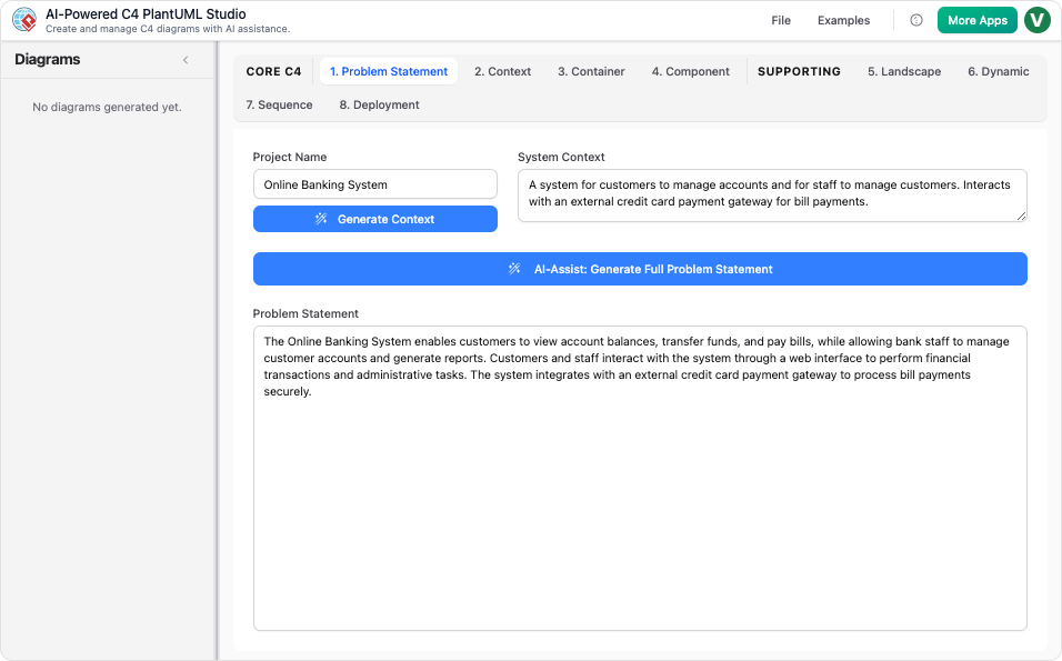
Text-to-Code Precision
Accuracy is paramount in technical modeling. The C4-PlantUML Studio transforms plain-text descriptions into valid PlantUML code. This feature is particularly vital for UML diagrams, ensuring that the diagrams are not just static images but are precise, editable, and version-controllable artifacts. This approach supports “Docs-as-Code” methodologies, allowing architecture to evolve alongside the codebase.

Conversational Refinement
Visual Paradigm enables users to update both C4 and UML models through simple dialogue. Commands such as “Add a payment gateway” or “Rename the controller class” trigger instant updates to the visual model and the underlying code. This reduces the friction of context switching and keeps documentation in sync with evolving requirements.
Unified Environment and Traceability
Consistency is the hallmark of good architecture. Visual Paradigm ensures traceability, meaning changes made in a high-level C4 diagram can be reflected in linked UML diagrams within the same project environment. Furthermore, the seamless import/export capabilities allow diagrams generated via AI to be brought into the Visual Paradigm Desktop for advanced manual editing and integration with other standards like SysML or ArchiMate.
The “GPS” Analogy
To visualize this integration, consider the analogy of navigating with a modern GPS system:
- The C4 Model represents the high-level route map. It shows the cities (systems), major highways (relationships), and destinations, helping you understand the overall journey and context.
- UML Diagrams represent the specific turn-by-turn instructions and complex lane layouts at intersections. They tell you exactly how to navigate a specific roundabout or interchange.
- Visual Paradigm’s AI Studio acts as the intelligent assistant that seamlessly switches between the “city view” and the “street view” the moment you ask for it.
By leveraging both standards within a unified AI-driven environment, architects no longer have to choose between clarity and detail—they can deliver both.
-
Ultimate Guide to C4 Model Visualization Using Visual Paradigm’s AI Tools: A comprehensive guide on leveraging Visual Paradigm’s AI-powered tools to automate and enhance C4 model visualization for faster, smarter software architecture design.
-
Leveraging Visual Paradigm’s AI C4 Studio for Streamlined Architecture Documentation: A detailed guide on using Visual Paradigm’s AI-enhanced C4 Studio to create clean, scalable, and maintainable software architecture documentation.
-
The Ultimate Guide to C4-PlantUML Studio: Revolutionizing Software Architecture Design – Visual Paradigm Blog: 2 weeks ago – Software architecture documentation is often a bottleneck—time-consuming, error-prone, and quickly outdated. The C4-PlantUML Studio, developed by Visual Paradigm, changes this by combining AI-driven automation, the C4 model’s clarity, and PlantUML’s flexibility into a single, powerful tool.
-
A Comprehensive Guide to Visual Paradigm’s AI-Powered C4 …: Dec 3, 2025 · Enter Visual Paradigm ’s AI-Powered C4 PlantUML Studio, released November 14, 2025 — a purpose-built tool that transforms natural language into correct, layered C4 diagrams. But how is it different from just asking ChatGPT or Claude to “draw a system diagram”? And can it really generate valid C4? Let’s unpack it all.
-
C4-PlantUML Studio | AI-Powered C4 Diagram Generator – Visual Paradigm: An AI-powered tool to automatically generate C4 software architecture diagrams from simple text descriptions.
-
Comprehensive Tutorial: Generating and Modifying C4 Component …: Dec 16, 2025 · This tutorial is based on the official Visual Paradigm product demo video, demonstrating how to use the AI-powered Chatbot to create and iteratively refine a C4 Component Diagram for a car park booking system. The C4 model (Context, Containers, Components, and Code) is a popular approach for visualizing software architecture, and the Component level focuses on the internal structure of a …
-
AI-Powered C4 Diagram Generator – Visual Paradigm AI: C4 & Supporting Diagrams The AI-Powered C4 Diagram Generator supports the four core levels of the C4 Model (Context, Container, Component, Deployment) plus essential supporting views to provide comprehensive architectural documentation. Core C4 Diagrams The Core C4 Diagrams are fundamental for documenting the static structure of your software system, detailing how it is broken down …
-
Visual Paradigm Full C4 Model Support Release: This release announcement details the integration of full C4 model support in Visual Paradigm, enabling users to create and manage architecture diagrams at multiple abstraction levels.
-
New: Full C4 Model Support Added to Visual Paradigm Desktop – ArchiMetric: 6 days ago · The C4 Model: A Comprehensive Guide to Visualizing Software Architecture with AI-Powered Tools …
-
Visual-paradigm: Our AI supports a wide range of diagrams across various domains, including UML, C4 models for software architecture, and strategic frameworks like SWOT and PESTLE analysis.
-
Visual Paradigm AI Suite: A Comprehensive Guide to Intelligent Modeling Tools – Cybermedian: 6 days ago – Strategic Frameworks: SWOT Analysis, PEST/PESTLE Analysis, Ansoff Matrix, and Blue Ocean Four Actions Framework. Systems Engineering: SysML Block Definition, Internal Block, and Requirement diagrams. Architecture: ArchiMate diagrams and C4 models. General Business: Organization Charts, Mind Maps, and PERT Charts. While the AI Chatbot is a cloud-based feature of VP Online, it is seamlessly integrated into the Visual Paradigm Desktop environment.
-
Visual-paradigm: Our AI supports a wide range of diagrams across various domains, including UML, C4 models for software architecture, and strategic frameworks like SWOT and PESTLE analysis.

