Software systems evolve. Requirements change, teams grow, and deadlines shift. Over time, this natural evolution often leads to a state of significant technical debt. The codebase becomes a tangled web of dependencies, making maintenance difficult and feature additions risky. One of the most effective ways to understand and untangle this complexity is through architectural visualization, specifically using package diagrams. This guide details a comprehensive case study on refactoring legacy code using package diagrams to restore clarity and maintainability to a struggling system.
Legacy code is not merely old code; it is code that is difficult to modify without introducing defects. The challenge lies not just in writing new features, but in understanding the existing structure. Visualizing the high-level organization of software components allows engineers to see the forest rather than getting lost in the trees. By mapping out packages, dependencies, and interfaces, teams can identify hotspots of coupling and plan strategic refactoring efforts.
Understanding Package Diagrams 📐
A package diagram is a UML (Unified Modeling Language) artifact used to show the organization of a system’s components. It groups related elements into packages, which represent logical boundaries. These diagrams are crucial for understanding the macro-structure of an application.
- Package: A namespace that contains related classes, interfaces, or other packages. It helps manage complexity by grouping functionality.
- Dependency: A relationship indicating that one package requires another to function. In diagrams, this is often shown with a dashed arrow.
- Coupling: The degree of interdependence between software modules. Low coupling is a primary goal in refactoring.
- Cohesion: The degree to which elements within a package belong together. High cohesion indicates a well-defined responsibility.
When dealing with legacy systems, reverse-engineering is often necessary. This means analyzing the existing code to create a package diagram that represents the current state. This “As-Is” model serves as the baseline for any refactoring initiative.
Case Study Background: The Enterprise Billing System 💰
For this case study, we examine a fictional mid-sized enterprise application known as the “Enterprise Billing System.” This system was originally built five years ago to handle monthly invoices for a subscription service. Over time, new features were added to support multi-currency, tax calculations, and third-party integrations.
The Problem: Development velocity had slowed significantly. Simple changes, such as updating a tax rate, required modifications across multiple files. Bugs were frequently introduced in unrelated modules. The team could not confidently deploy new features without regression testing the entire system.
The Goal: The objective was to reduce coupling between modules, improve testability, and create a modular architecture that supports future growth without requiring a complete rewrite.
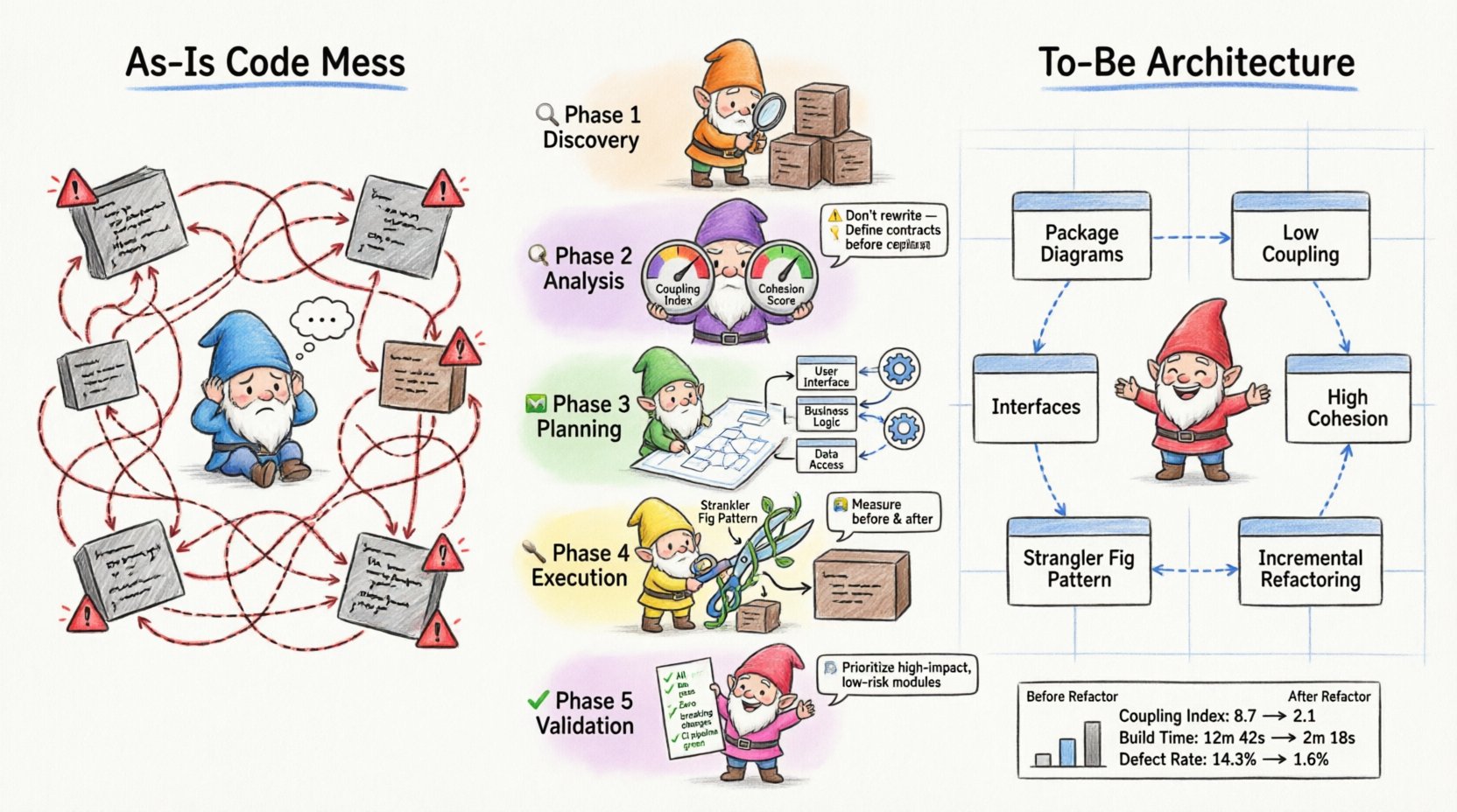
Phase 1: Discovery and Inventory 🔍
The first step in any refactoring effort is understanding the current state. Without a map, navigation is impossible. In this phase, the team focused on reverse-engineering the codebase to create a baseline package diagram.
1.1 Identifying Boundaries
The team began by listing all existing namespaces or modules. They documented every file and directory to understand the physical structure. This inventory revealed that several distinct business domains were mixed within the same directories.
- Core Billing: Contains logic for invoice generation and pricing.
- Reporting: Contains logic for generating PDFs and CSV exports.
- Integration: Contains logic for connecting to external payment gateways.
- Utilities: Contains shared helper functions, date parsers, and string formatters.
1.2 Mapping Dependencies
Once the components were identified, the team mapped how they interacted. They used automated tools to trace import statements and method calls. This data was manually verified to ensure accuracy.
The resulting “As-Is” package diagram revealed significant issues:
- The Reporting package directly instantiated classes from Core Billing.
- The Utilities package contained logic specific to billing, violating separation of concerns.
- Circular dependencies existed between Integration and Core Billing.
Phase 2: Analysis of Coupling and Cohesion 🧩
With the diagram complete, the team analyzed the structural health of the system. They looked for signs of high coupling and low cohesion, which are indicators of technical debt.
2.1 Identifying God Objects
A “God Object” is a class or module that knows too much or does too much. In the legacy system, a central class named Manager was responsible for handling user authentication, billing logic, and report generation. This violated the Single Responsibility Principle.
2.2 The Dependency Problem
The team created a dependency matrix to visualize the flow of information. A matrix with too many dark cells indicates a system where everything depends on everything else.
| Package A | Package B | Dependency Type | Impact |
|---|---|---|---|
| Reporting | Core Billing | Direct Import | High Risk: Changes in billing break reports. |
| Utilities | Core Billing | Direct Import | Medium Risk: Shared state issues. |
| Integration | Reporting | Indirect Import | Low Risk: But creates tight coupling over time. |
The analysis confirmed that the Reporting module was too tightly coupled to the Core Billing module. If the billing logic changed, the reporting team had to update their code immediately. This bottleneck slowed down development.
Phase 3: Planning the Target State 🗺️
Refactoring requires a target. The team defined the “To-Be” architecture. The goal was to separate concerns so that changes in one area would not ripple into others.
3.1 Defining Interfaces
Interfaces act as contracts between packages. By defining clear interfaces, packages can interact without knowing the internal implementation details of the other. The team identified key interaction points:
- Billing Service: Exposes methods for calculating amounts and creating invoices.
- Invoice Repository: Handles data persistence for invoices.
- Notification Service: Handles sending emails and alerts.
3.2 Redrawing the Diagram
Using the identified interfaces, the team drew the new package diagram. Key changes included:
- Decoupling Reporting: The Reporting package would no longer import Core Billing classes. Instead, it would consume data via a read-only DTO (Data Transfer Object) interface.
- Centralizing Utilities: Utility functions specific to billing were moved into the Core Billing package. Only generic utilities remained in the global Utilities package.
- Breaking Circular Dependencies: The Integration package was refactored to depend on a generic Payment Interface, not the specific Billing implementation.
Phase 4: Execution Strategy 🛠️
Refactoring legacy code is risky. The team adopted a cautious, iterative approach to minimize the chance of breaking production functionality.
4.1 The Strangler Fig Pattern
The team utilized a pattern where new functionality is built in the new structure, while old functionality is gradually migrated. This allows the system to remain functional at all times.
- Step 1: Create the new interfaces in the target packages.
- Step 2: Implement the new logic in the target packages.
- Step 3: Route traffic from the old code to the new code.
- Step 4: Delete the old code once coverage is sufficient.
4.2 Incremental Refactoring
The team broke down the work into small, verifiable tasks. They focused on one package at a time. For example, they started with the Utilities package because it was the least risky.
Actions taken:
- Extracted date formatting logic from the Utilities package into the Core Billing package.
- Created a new interface for data retrieval.
- Updated the Reporting package to use the new interface.
- Wrote unit tests to verify the new interface behavior.
Phase 5: Validation and Maintenance ✅
After the structural changes were implemented, validation was critical. The team ensured that the system behaved exactly as it did before, but with improved internal structure.
5.1 Regression Testing
Automated test suites were run to ensure no functionality was lost. The team paid special attention to edge cases that had caused bugs in the past.
5.2 Continuous Monitoring
Even after refactoring, the system must be monitored. The team established guidelines for future development to prevent the re-emergence of the same anti-patterns.
- Dependency Rules: New code must adhere to the dependency direction defined in the target package diagram.
- Code Reviews: Architects review pull requests to ensure package boundaries are respected.
- Documentation: Package diagrams are updated whenever the architecture changes significantly.
Key Lessons Learned 📚
This case study highlights several critical takeaways for teams undertaking similar refactoring initiatives.
1. Visualization is Essential
You cannot fix what you cannot see. Package diagrams provided the visibility needed to understand the scope of the problem. Without them, the team would have been guessing about dependencies.
2. Interfaces Drive Decoupling
Defining clear interfaces allowed teams to work independently. The Reporting team could proceed with their work once the interface was defined, without waiting for the Billing team to finish their internal logic.
3. Incremental Changes Win
Trying to refactor everything at once is a recipe for failure. Small, verified steps build confidence and reduce risk. The Strangler Fig pattern allowed the team to migrate functionality safely.
4. Maintenance is Continuous
Refactoring is not a one-time event. It is a discipline. The team had to commit to updating diagrams and enforcing rules to prevent the system from degrading again.
Common Pitfalls to Avoid ⚠️
Even with a good plan, teams often stumble during the execution phase. Here are common mistakes to watch out for.
- Over-Engineering: Creating too many layers of abstraction can slow down development. Keep interfaces simple and focused on immediate needs.
- Ignoring Tests: Never refactor without a safety net. If you do not have unit tests, write them first. They are your safety net.
- Ignoring the Business: Refactoring should support business goals. If a refactor does not improve velocity or stability, it may not be worth the effort.
- Stale Diagrams: An outdated package diagram is worse than no diagram. It gives a false sense of security. Keep diagrams synchronized with code.
Metrics for Success 📊
How do you know the refactoring was successful? The following metrics can help measure improvement.
| Metric | Before Refactoring | After Refactoring |
|---|---|---|
| Coupling Index | High (Many dependencies) | Low (Few dependencies) |
| Cyclomatic Complexity | Complex logic in single files | Simplified logic across modules |
| Build Time | Slow (Full recompilation) | Faster (Incremental builds) |
| Defect Rate | High | Reduced |
Tracking these metrics over time helps demonstrate the value of architectural work to stakeholders.
Final Considerations for Sustainable Architecture 🏗️
Refactoring legacy code is a marathon, not a sprint. It requires patience, discipline, and a clear vision. By using package diagrams to visualize the system, teams can make informed decisions about where to invest their effort.
The process of creating the diagram is often more valuable than the diagram itself. The act of mapping dependencies forces the team to understand the system deeply. This shared understanding is the foundation of a healthy codebase.
Remember that architecture is not just about structure; it is about communication. A package diagram communicates the design intent to new team members. It reduces the cognitive load required to onboard and contribute to the project.
As you embark on your own refactoring journey, keep the focus on incremental improvement. Do not aim for perfection in the first pass. Aim for progress. Every small reduction in coupling is a win. Every interface added is a step toward a more maintainable system.
By following these principles and utilizing package diagrams as a tool for analysis and planning, you can transform a tangled legacy system into a robust, modular architecture. This approach ensures that the software can evolve alongside the business needs it serves.