Software architecture relies heavily on clear communication. When teams discuss complex systems, visual aids become essential for understanding structure without getting lost in code. A package diagram serves this exact purpose. It offers a high-level view of how a system is organized into logical groupings. These groupings help manage complexity by separating concerns. Understanding the core components of a package diagram is fundamental for anyone involved in system design or software development. This guide provides a detailed breakdown of the elements involved, their relationships, and how they contribute to a maintainable architecture.
Understanding the Package Diagram Concept 🧩
A package diagram is a type of Unified Modeling Language (UML) diagram. It focuses on the organizational structure of a system rather than the behavior of individual objects. In the context of software engineering, a package represents a namespace that contains related elements. These elements could be classes, interfaces, or even other packages. The primary goal is to reduce complexity by grouping similar functionality together.
Consider a large application. It might have modules for authentication, data access, user interface, and business logic. Without a package diagram, these modules might appear as a tangled web of dependencies. With a package diagram, the separation is clear. Developers can see which parts of the system rely on others. This visibility is crucial for impact analysis. When a change is proposed in one area, the diagram shows the ripple effects on other areas.
Why Use Package Diagrams? 📊
- Clarification of Structure: They provide a roadmap of the system layout.
- Dependency Management: They highlight how components interact.
- Team Collaboration: They allow different teams to work on different packages with defined boundaries.
- Documentation: They serve as living documentation for the system architecture.
- Scalability Planning: They help identify where the system can grow or needs refactoring.
Core Component: The Package Element 📦
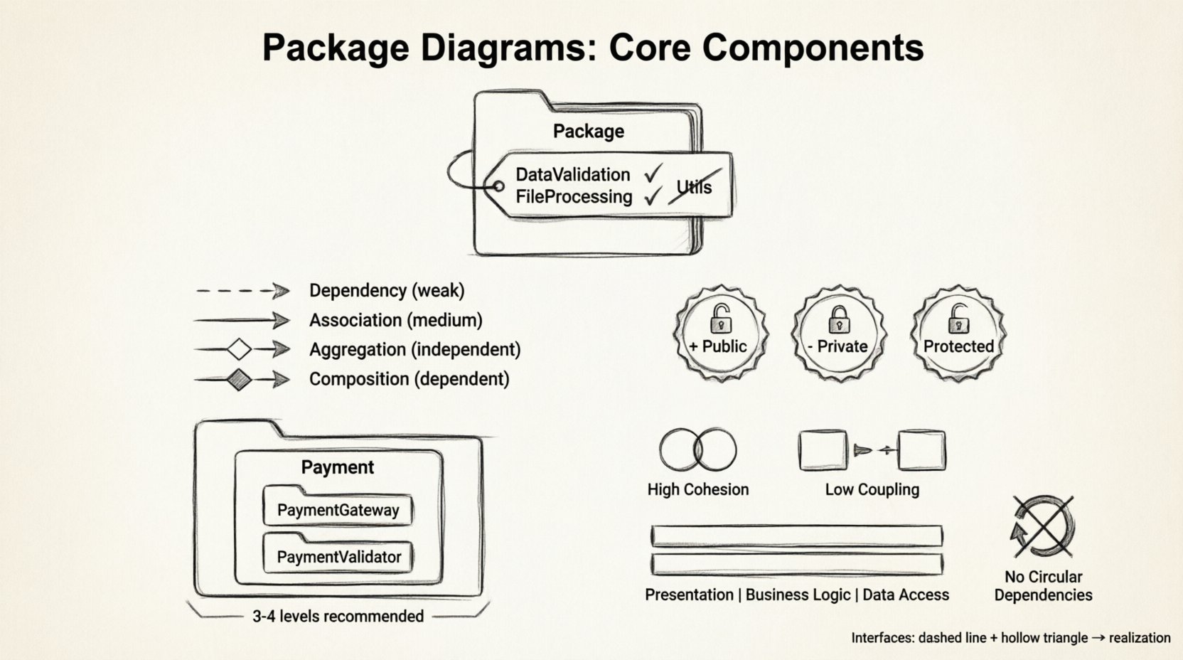
The package itself is the primary building block of this diagram. Visually, it is often represented as a folder icon or a rectangle with a tab. This visual cue immediately signals to the reader that this is a container. However, the visual representation is secondary to the logical definition.
Naming Conventions 🏷️
Names are critical for navigation. A package name should be descriptive yet concise. It should reflect the content contained within. Poor naming leads to confusion. For example, a package named Utils is too vague. It does not indicate what kind of utilities are present. A better name might be DataValidation or FileProcessing.
Consider the following guidelines for naming:
- Use Namespace Terminology: Align with the underlying programming language conventions.
- Be Consistent: If you use
CamelCasefor one package, do not usesnake_casefor another. - Avoid Ambiguity: Ensure the name does not overlap with other common terms in the domain.
- Reflect Hierarchy: Names should often imply the folder structure.
Stereotypes and Metadata 📝
Packages can carry additional information known as stereotypes. These are annotations that provide context about the package’s role. For instance, a package might be marked as {interface} or {implementation}. This helps distinguish between the contract and the realization of a feature. Metadata can also include version numbers or author information directly on the package element.
Relationships and Dependencies 🔗
A package diagram is not just a collection of boxes. The lines connecting them are just as important. These lines represent relationships. They define how information flows between the logical groupings. Misunderstanding these relationships can lead to tightly coupled systems that are difficult to modify.
Dependency Relationship 🔗
The dependency is the most common relationship. It indicates that one package uses another. If the implementation of the target package changes, the source package might need to change as well. This is a directional link. It flows from the dependent package to the depended package.
- Usage: Package A uses classes from Package B.
- Visibility: Often shown as a dashed arrow.
- Impact: Changes in B affect A.
Association and Aggregation 🔗
While dependencies are common, associations describe a stronger structural link. An association implies that one package has knowledge of another package’s existence. Aggregation is a specific type of association where one package contains another, but the contained package can exist independently.
Composition 🔗
Composition is a stronger form of aggregation. It implies ownership. If the parent package is removed, the child package ceases to exist. This relationship defines a lifecycle dependency. It is often used to describe cohesive units of work.
Comparison of Relationship Types
| Relationship Type | Direction | Strength | Lifecycle Impact |
|---|---|---|---|
| Dependency | Dashed Arrow | Weak | None |
| Association | Solid Line | Medium | None |
| Aggregation | Hollow Diamond | Medium | Independent |
| Composition | Filled Diamond | Strong | Dependent |
Visibility and Access Control 👁️
Not all elements within a package should be visible to the outside world. Access control is a vital concept in package diagrams. It defines the boundaries of the public API versus the internal implementation details. This separation supports the principle of information hiding.
Public Elements 🌍
Public elements are accessible from any package. They form the interface through which other parts of the system interact. In a diagram, these are often marked with a plus sign (+). Keeping the public surface area small reduces the risk of accidental misuse.
Private Elements 🔒
Private elements are restricted to the package itself. They are implementation details that should not be exposed. In a diagram, these are marked with a minus sign (-). This clarity helps developers understand what is safe to change and what is off-limits.
Protected Elements 🛡️
Protected elements are accessible to the package and its sub-packages. This is useful for inheritance hierarchies where derived classes need access to base functionality. It allows for extension without exposing the functionality to the entire system.
Interfaces and Realization 🎭
Interfaces define a contract. They specify what operations a package can perform without dictating how they are performed. This decoupling allows different packages to implement the same interface in different ways. It promotes flexibility.
Realization Relationship
Realization connects an interface to a package that implements it. It is often shown with a dashed line and a hollow triangle arrow pointing to the interface. This relationship is critical for understanding which packages fulfill specific functional requirements.
- Abstraction: Interfaces provide a high-level abstraction.
- Flexibility: Implementations can be swapped without affecting the user.
- Testing: Interfaces allow for easier mocking and testing strategies.
Nesting and Hierarchy 🌳
Complex systems often require deep organization. Nesting allows a package to contain other packages. This creates a tree structure. It helps manage large systems by breaking them down into smaller, manageable chunks.
Logical Grouping
Nesting should follow a logical hierarchy. For example, a Payment package might contain PaymentGateway and PaymentValidator sub-packages. This structure reflects the domain model. It makes navigation intuitive for developers.
Flat vs. Deep Hierarchy
There is a balance to be struck between flat and deep hierarchies.
- Flat Hierarchy: Easy to find elements, but can lead to cluttered package names.
- Deep Hierarchy: Clear separation, but can make navigation tedious.
It is generally recommended to limit the depth of nesting. Too many levels can obscure the relationships between packages. A depth of three to four levels is usually sufficient for most enterprise systems.
Documentation and Metadata 📄
A package diagram is a visual tool, but it needs textual support. Notes and comments provide the necessary context that icons cannot convey. They explain the reasoning behind a design decision.
Using Notes
Notes can be attached to any element. They are useful for:
- Explaining complex business rules.
- Documenting technical debt or known limitations.
- Providing links to external specifications.
- Clarifying naming choices.
Tagged Values
Tagged values allow for custom attributes. You might tag a package with its version, owner, or review status. This metadata turns the diagram into a management tool, not just a design tool.
Best Practices for Maintainability 🛠️
Creating a diagram is one thing; maintaining it is another. A diagram that is not kept up to date becomes a liability. It misleads developers and causes errors. Adhering to best practices ensures the diagram remains a valuable asset.
High Cohesion
Elements within a package should be closely related. If a package contains unrelated classes, it violates the Single Responsibility Principle. High cohesion means the package has a single, well-defined purpose. This makes the package easier to understand and modify.
Low Coupling
Dependencies between packages should be minimized. High coupling means that a change in one package forces changes in many others. This creates fragility. Aim for dependencies to flow in one direction where possible.
Layering
Organize packages into layers. A common pattern includes Presentation, Business Logic, and Data Access layers. Packages in a lower layer should not depend on packages in a higher layer. This enforces architectural boundaries and prevents circular dependencies.
Avoid Circular Dependencies
A circular dependency occurs when Package A depends on Package B, and Package B depends on Package A. This creates a cycle that can lead to initialization errors and testing difficulties. The diagram should ideally be a Directed Acyclic Graph (DAG).
Common Pitfalls to Avoid ⚠️
Even experienced architects make mistakes. Recognizing common pitfalls can save time and effort.
- Over-Diagramming: Including every class in the diagram makes it unreadable. Package diagrams are for high-level views.
- Inconsistent Notation: Using different arrow styles for the same relationship confuses readers.
- Ignoring Visibility: Not distinguishing between public and private elements hides the true API surface.
- Static Design: Treating the diagram as a one-time artifact rather than evolving it with the code.
- Generic Names: Using names like
Module1orComponentprovides no value.
Integration with Codebases 💻
Modern development environments often allow for synchronization between code and diagrams. This ensures that the visual representation matches the source code. While manual updates are possible, automated synchronization reduces the risk of drift.
Generation vs. Design
Sometimes, diagrams are generated from code (reverse engineering). Sometimes, code is generated from diagrams (forward engineering). Both approaches have merits.
- Reverse Engineering: Good for understanding legacy systems.
- Forward Engineering: Good for planning new systems before coding begins.
The Role of Package Diagrams in Agile 🚀
In Agile methodologies, documentation is often viewed with skepticism. However, package diagrams are lightweight enough to be useful without slowing down development. They provide the necessary architectural context without the overhead of detailed design documents.
Just-in-Time Design
Create diagrams when a new feature requires significant structural changes. This approach ensures the diagram remains relevant. Do not spend time documenting features that might change in the next sprint.
Team Alignment
Use the diagram in planning sessions. It helps the team agree on boundaries before writing code. This alignment reduces the need for refactoring later. It acts as a contract between teams working on different parts of the system.
Conclusion on Architecture Clarity 🧭
Package diagrams are a fundamental tool for managing software complexity. They transform abstract code into a structured map. By understanding the core components—packages, dependencies, visibility, and interfaces—teams can build systems that are easier to maintain and scale. The key lies in consistency and discipline. Regularly review the diagrams to ensure they reflect the current state of the codebase. Avoid the temptation to over-complicate the visual representation. Keep it simple, clear, and focused on the relationships that matter most.
When used correctly, these diagrams facilitate communication across the organization. They bridge the gap between business requirements and technical implementation. They serve as a common language for architects, developers, and stakeholders. Investing time in creating accurate package diagrams pays dividends in reduced technical debt and improved system stability over time. The effort spent on clarity upfront prevents confusion and rework later.