A Package Diagram serves as a fundamental tool in the architecture of complex software systems. It provides a high-level view of how different parts of a system interact, organize, and depend on one another. For those new to software modeling, understanding this diagram type is crucial for maintaining codebases that are scalable and manageable. This guide explores the core concepts, structural elements, and practical applications of Package Diagrams without relying on specific commercial tools.
🤔 What is a Package Diagram?
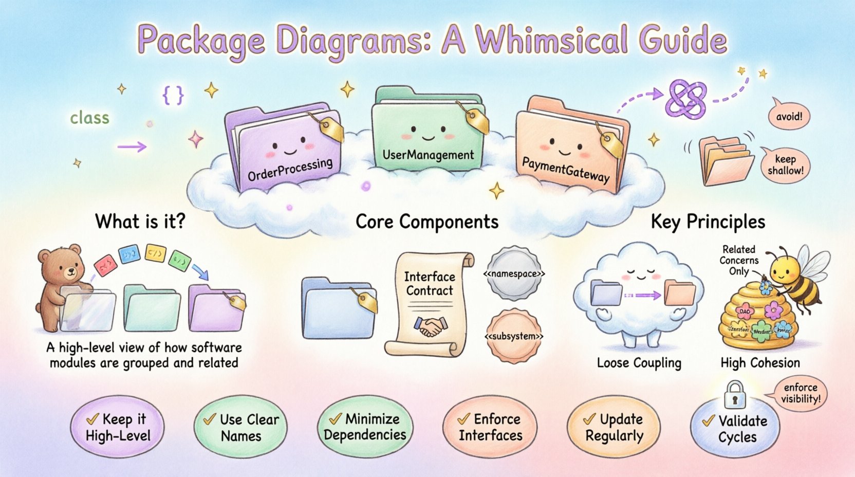
In the context of Unified Modeling Language (UML), a Package Diagram is a structural diagram that organizes elements into groups called packages. Think of it as a file system for your software architecture. Just as folders on a computer hard drive group related files together to keep things tidy, packages group related classes, interfaces, and other components.
- Namespace Management: Packages provide a namespace, preventing naming conflicts between different parts of a system.
- Logical Grouping: They allow developers to visualize the system’s logical structure rather than its physical implementation.
- Abstraction: They hide internal details of a module, showing only what is necessary for external interaction.
When you are designing a large application, the codebase can quickly become overwhelming. A Package Diagram helps you step back and see the forest instead of just the trees. It is not about drawing every single line of code; it is about defining the boundaries and relationships between major functional areas.
🧱 Core Components of a Package Diagram
Understanding the building blocks is the first step to creating effective diagrams. These elements work together to define the structure of your system.
1. Packages
The primary element is the package itself. It is typically represented as a tabbed folder icon. Inside a package, you can place:
- Classes
- Interfaces
- Other Packages (sub-packages)
- Components
- Nodes
Each package should have a clear name that reflects its responsibility. For example, in an e-commerce system, you might see packages named OrderProcessing, UserManagement, and PaymentGateway.
2. Interfaces
Interfaces define a contract. They specify what operations a package or class can perform without revealing how those operations are implemented. In a Package Diagram, interfaces are critical for decoupling systems. They allow one package to depend on an interface rather than a concrete implementation, making the system more flexible to changes.
3. Stereotypes
Stereotypes extend the vocabulary of UML. They are used to classify a specific type of model element. Common stereotypes in package diagrams include:
- <<namespace>>: Indicates a package containing other elements.
- <<subsystem>>: Denotes a distinct part of a system with its own behavior.
- <<boundary>>: Represents the interface between the system and the outside world.
🔗 Relationships and Dependencies
The power of a Package Diagram lies in how it connects these packages. Relationships define the flow of information and control between different parts of the system. Mismanagement of these connections is a common source of technical debt.
Dependency
This is the most common relationship. It indicates that one package uses or relies on another. If the target package changes, the source package may be affected. Dependencies are usually depicted as a dashed arrow pointing from the source to the target.
- Use Case: The
ReportGeneratorpackage depends on theDataExtractorpackage to fetch information. - Implication: High dependency counts increase the risk of ripple effects during maintenance.
Association
An association represents a structural relationship between packages. It implies a stronger connection than a dependency. This might mean one package holds a reference to another as a permanent attribute.
Generalization
Also known as inheritance, this relationship indicates that one package is a specialized version of another. This is less common at the package level but can occur when defining a hierarchy of subsystems.
Realization
Realization occurs when a package implements an interface defined by another package. This is often shown with a dashed line and a hollow triangle arrowhead.
Dependency Types
Not all dependencies are created equal. Understanding the nuances helps in maintaining a healthy architecture.
| Dependency Type | Description | Example |
|---|---|---|
| Usage | A simple usage relationship where one element calls another. | Calling a function in another package. |
| Import | Public elements are visible in the importing package. | Importing a library of utilities. |
| Access | Accesses private or protected elements (rare in high-level design). | Internal debugging mechanisms. |
| Instantiation | One package creates instances of classes in another. | Factory pattern implementation. |
🏗️ Architectural Principles: Coupling and Cohesion
A well-constructed Package Diagram is a direct reflection of sound software engineering principles. Two concepts stand out above the rest: Coupling and Cohesion.
Coupling
Coupling refers to the degree of interdependence between software modules. In the context of a Package Diagram, you want to minimize coupling. Tight coupling means that changes in one package will likely break or require changes in another package. This creates fragility.
- Loose Coupling: Packages interact through well-defined interfaces. They know little about each other’s internal implementation.
- High Coupling: Packages share data structures or rely on internal details of other packages. This is difficult to maintain.
Cohesion
Cohesion refers to how closely related the responsibilities of a single package are. High cohesion means a package does one thing and does it well. Low cohesion means a package tries to do too many unrelated things.
- Functional Cohesion: All elements in the package contribute to a single, well-defined purpose.
- Coincidental Cohesion: Elements are grouped together arbitrarily. This is the lowest form of cohesion and should be avoided.
When drawing your diagram, aim for packages that are highly cohesive and loosely coupled. This separation allows teams to work on different parts of the system with minimal conflict.
📐 Visual Notation Standards
While specific tools may vary slightly, the visual language of Package Diagrams follows standard UML conventions. Adhering to these standards ensures that anyone reading the diagram understands the intent.
- Folder Icon: The standard representation for a package. It often has a small tab on the top left.
- Label Placement: The package name is placed inside the folder. If the package contains many elements, a tabbed view is often used.
- Line Styles:
- Solid lines typically represent associations or generalizations.
- Dashed lines represent dependencies or interfaces.
- Arrowheads indicate direction.
- Visibility Indicators:
- +: Public (accessible from anywhere).
- –: Private (accessible only within the package).
- #: Protected (accessible within the package and subclasses).
📅 When to Use Package Diagrams
Not every project requires a package diagram. They are most valuable when complexity increases. Here are specific scenarios where they are essential.
1. Large-Scale Systems
When a system has hundreds of classes, navigating the code becomes impossible without a map. A package diagram provides the macro view needed to locate functionality quickly.
2. Refactoring Projects
If you are moving code from one part of the system to another, a package diagram helps you understand the impact. You can visualize which other packages will be affected by the move before writing a single line of code.
3. Onboarding New Developers
New team members often struggle to understand the project structure. A package diagram acts as a roadmap, explaining how the modules relate to each other without forcing them to read the code immediately.
4. Microservices Architecture
In distributed systems, packages often map to microservices. Visualizing these boundaries helps in understanding data flow and service dependencies across the network.
🛠️ Building a Package Diagram: Step-by-Step
Creating a diagram is an iterative process. It is not something you do once and forget. Follow these steps to build a robust model.
Step 1: Identify Boundaries
Start by listing the major functional areas of your system. Ask yourself, “What are the main capabilities this system offers?” These capabilities become your candidate packages. Do not worry about being too granular at this stage.
Step 2: Group Elements
Assign your classes and components to these packages. If a class fits into multiple packages, choose the one where it is most logically centered. If a class belongs to a sub-system, create a sub-package.
Step 3: Define Interfaces
Before drawing lines between packages, define the interfaces they expose. What does Package A need to ask Package B to do? Document these contracts. This step ensures that dependencies are based on abstractions, not implementations.
Step 4: Map Dependencies
Draw the lines connecting the packages. Be honest about the direction. Does A call B, or does B call A? Ensure that the arrows point in the direction of the usage (from user to provider).
Step 5: Review and Refine
Check for circular dependencies. A package should not depend on another package that depends on it. This creates a cycle that can lead to initialization errors and logical deadlocks. If cycles exist, introduce an intermediary interface or break the relationship.
⚠️ Common Pitfalls to Avoid
Even experienced architects make mistakes. Being aware of common errors can save you significant time later.
1. Spaghetti Dependencies
When packages are connected in a web-like structure with no clear hierarchy, it becomes a “spaghetti architecture.” This makes it hard to determine where a change will propagate. Aim for a layered or hierarchical structure.
2. Over-Nesting
Creating too many levels of sub-packages can make the diagram confusing. A package name like Root.Sub1.Sub2.Sub3 is hard to remember. Keep the depth shallow. If you need more grouping, rename the package rather than nesting it further.
3. Ignoring Visibility
Marking everything as public creates a loose structure where any package can access any class. This leads to tight coupling. Enforce strict visibility rules. Private elements should remain private to their package.
4. Mixing Concerns
Do not put database access code in the same package as user interface logic. This violates the Single Responsibility Principle. Group by concern (e.g., Infrastructure, Domain, Presentation).
📊 Comparison: Package vs. Other Diagrams
It is easy to confuse Package Diagrams with Class or Component Diagrams. Understanding the distinction is key to using the right tool for the job.
| Diagram Type | Focus | Best Used For |
|---|---|---|
| Package Diagram | Logical grouping and namespaces. | High-level system structure and organization. |
| Class Diagram | Attributes and methods of classes. | Detailed object-oriented design and data structures. |
| Component Diagram | Physical implementation units. | Deployment and executable file structures. |
| Sequence Diagram | Interaction over time. | Understanding specific workflows and message flows. |
Use Package Diagrams when you need to explain the organization. Use Class Diagrams when you need to explain the data. Use Component Diagrams when you need to explain the build process.
🚀 Advanced Topics
As you become more comfortable with the basics, you can explore advanced concepts that refine your modeling capabilities.
1. Circular Dependencies
A circular dependency occurs when Package A depends on Package B, and Package B depends on Package A. This is often a sign of poor design. To resolve this, you can:
- Extract a shared interface into a third package.
- Refactor the code to reduce the need for interaction.
- Use dependency injection to break the compile-time link.
2. Aggregation and Composition
While more common in Class Diagrams, these concepts apply to packages. Composition implies a stronger ownership relationship. If a package is composed of another, the child package cannot exist without the parent. Aggregation implies a weaker relationship where the child can exist independently.
3. Documentation Integration
Modern modeling tools allow you to embed documentation directly into the package diagram. You can add notes describing the purpose of a package, its author, or its version history. This turns the diagram into a living document.
❓ Frequently Asked Questions
Q: Do I need a package diagram for a small project?
For small projects with fewer than 50 classes, a package diagram may be overkill. The code structure is often obvious. However, if you anticipate growth, creating the diagram early can save time later.
Q: Can a package diagram change over time?
Yes, absolutely. As the system evolves, packages may be merged, split, or renamed. The diagram should be updated whenever the architecture changes. An outdated diagram is worse than no diagram at all.
Q: How do I handle legacy code?
When documenting legacy systems, start by analyzing the existing file structure. Create the packages based on how the code is currently organized, then identify areas that need refactoring. Use the diagram as a tool to plan the migration.
Q: Is UML required to use Package Diagrams?
While UML is the standard, the concept of grouping and mapping dependencies exists independently. You can use these principles in any modeling environment, even if you do not strictly adhere to UML syntax.
📝 Summary of Best Practices
To ensure your Package Diagrams remain useful throughout the lifecycle of your project, adhere to the following checklist:
- Keep it High-Level: Avoid cluttering the diagram with individual methods or attributes.
- Use Clear Names: Package names should be descriptive and consistent.
- Minimize Dependencies: Aim for a star or layered topology rather than a mesh.
- Enforce Interfaces: Depend on abstractions, not concrete classes.
- Update Regularly: Treat the diagram as part of the code review process.
- Validate Cycles: Ensure there are no circular dependencies between packages.
By following these guidelines, you create a map that not only guides your current development but also serves as a reference for future maintainers. The effort invested in drawing these diagrams pays dividends in reduced bugs and faster feature implementation.
🔍 Final Thoughts
A Package Diagram is more than just a drawing; it is a communication tool. It bridges the gap between technical implementation and business requirements by organizing complexity into manageable chunks. Whether you are planning a new system or maintaining an old one, the ability to visualize the structure of your software is an essential skill. Focus on clarity, maintainability, and logical grouping, and your architecture will stand the test of time.