Software architecture is often described as the bridge between business needs and technical implementation. Requirements documents are dense with text, filled with constraints, behaviors, and user stories. Package diagrams provide the visual structure needed to make sense of that complexity. This guide explains the translation process from raw specification to structured visual representation. 🏗️
When developers read a requirements document, they see functionality. When architects view a package diagram, they see boundaries, responsibilities, and interactions. Moving between these two perspectives requires discipline. It is not merely about drawing boxes; it is about understanding the logical flow of data and control within the system. This article details the methodology for creating accurate package views that reflect the underlying specifications.
Understanding the Foundation: Requirements Analysis 🔍
Before a single box is drawn on a canvas, the input material must be thoroughly understood. Requirements are not just a list of features; they are a set of constraints and capabilities. A package diagram represents the static structure of the software, so the requirements feeding into it must be static in nature.
- Functional Requirements: These describe what the system must do. In the context of packages, these often map to specific modules or services responsible for executing logic.
- Non-Functional Requirements: These describe how the system performs. Constraints like performance, security, and maintainability heavily influence package boundaries.
- Domain Concepts: The vocabulary used in the requirements often points to the entities that should reside within packages. Identifying nouns in the text is a common first step in defining package names.
Consider the phrase “The system must validate user credentials before accessing the dashboard.” This sentence contains multiple potential package boundaries. It involves authentication logic, user management, and dashboard access control. A naive approach might lump all of this into one large package. A structured approach separates concerns based on their stability and change frequency.
Categorizing Input Data
To ensure clarity during the translation phase, categorize requirements into logical buckets. This prevents the diagram from becoming a tangled web of dependencies.
| Requirement Type | Focus Area | Package Implication |
|---|---|---|
| Business Logic | Core processing rules | Core domain packages |
| Data Access | Storage and retrieval | Infrastructure or persistence packages |
| User Interface | Interaction and display | Presentation or API packages |
| External Interfaces | Third-party integrations | Adapter or gateway packages |
The Package Diagram Concept 🎨
A package is a namespace that organizes elements into groups. In software architecture, it represents a module of related functionality. Unlike classes or functions, packages operate at a higher level of abstraction.
The primary goal of a package diagram is to manage complexity. By grouping elements, you reduce the cognitive load on the reader. A developer looking at a system should be able to understand the high-level flow without diving into code immediately.
Key Principles of Package Design
- High Cohesion: Elements within a package should be closely related. If a package contains unrelated features, it indicates a design flaw.
- Low Coupling: Packages should depend on other packages through well-defined interfaces. Direct dependencies on internal implementation details create fragility.
- Visibility: Clearly define what is public and what is private. Packages should expose only what is necessary for interaction.
The Translation Process: Step-by-Step 🔄
Translating specifications into a visual model is an iterative process. It requires moving from abstract text to concrete structure. The following steps outline the workflow for creating a robust package view.
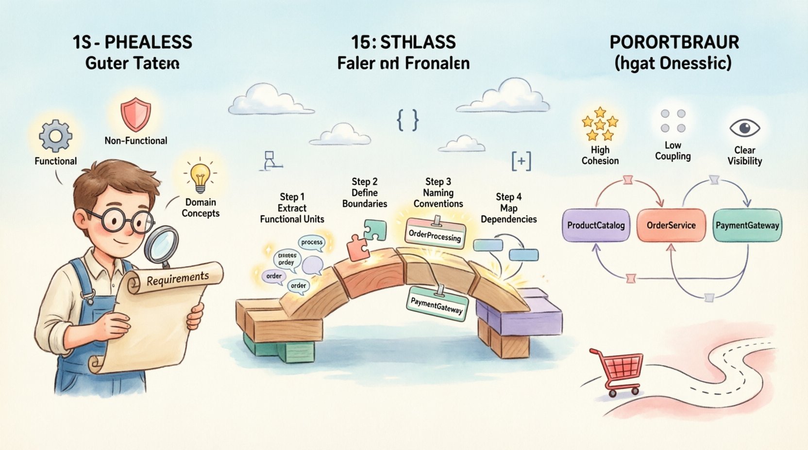
Step 1: Extraction of Functional Units
Read through the requirements and identify distinct functional units. Highlight verbs and objects. For example, “Process Payment” is a unit. “Store Customer Data” is another. These become the candidates for package names.
- Identify the actors involved in the requirement.
- Determine the outcome of the requirement.
- Group similar outcomes together.
Step 2: Defining Boundaries
Once you have a list of functional units, you must decide where to draw the lines. Boundaries are determined by the level of change required. If a feature changes frequently, it should be isolated in its own package to minimize impact on other parts of the system.
Ask these questions during boundary definition:
- Does this feature share data with another feature?
- Are these features used by the same external systems?
- Is there a logical separation of concerns (e.g., security vs. business logic)?
Step 3: Naming Conventions
Names matter. A package name should be descriptive and consistent. Avoid generic names like “Utils” or “Libs” unless the contents truly fit that description. Instead, use names that reflect the domain, such as “OrderProcessing” or “IdentityManagement”.
Consistency in naming helps stakeholders navigate the diagram. If one package is named “PaymentHandler,” another should not be “BillingService” unless they serve different purposes. Standardizing on a suffix or prefix pattern aids readability.
Step 4: Mapping Dependencies
The final step is to draw the relationships between packages. A dependency arrow indicates that one package uses another. These relationships should reflect the flow of control described in the requirements.
When mapping dependencies:
- Draw arrows from the caller to the callee.
- Ensure arrows do not cross unnecessarily.
- Use different line styles to indicate different types of dependencies (e.g., synchronous vs. asynchronous).
Managing Dependencies and Coupling ⚖️
Dependencies are the lifelines of a system, but they are also its greatest source of risk. High coupling means that a change in one package requires changes in many others. Low coupling allows for independent evolution of components.
The goal is to ensure that packages communicate through interfaces. An interface defines the contract between packages without exposing internal implementation. This abstraction is crucial for maintaining a stable architecture over time.
Types of Dependencies
Not all dependencies are created equal. Understanding the type of relationship helps in managing the complexity of the diagram.
- Usage: Package A calls a method in Package B.
- Realization: Package A implements an interface defined in Package B.
- Import: Package A requires the definition of a type in Package B.
- Access: Package A needs to access the internals of Package B (generally discouraged).
Avoiding Cycles
Cycles occur when Package A depends on Package B, and Package B depends on Package A. This creates a circular dependency that makes the system difficult to build and test. A package diagram should ideally be a directed acyclic graph.
If a cycle exists in the requirements, it usually indicates a need for refactoring. You may need to extract a common interface into a third package that both A and B depend on. This breaks the cycle and establishes a clear hierarchy.
Common Pitfalls in Translation ⚠️
Even experienced architects make mistakes when translating requirements to diagrams. Being aware of common pitfalls helps in producing cleaner, more maintainable models.
Pitfall 1: Over-Engineering
It is tempting to create a package structure that anticipates every future requirement. This leads to premature optimization. The diagram should reflect the current state of the requirements, not a hypothetical future state. Keep packages simple and focused.
Pitfall 2: Ignoring Non-Functional Requirements
Performance and security requirements often dictate architectural decisions. For example, if the system requires high availability, the package structure might need to support replication. If security is paramount, authentication packages must be isolated from business logic packages.
Pitfall 3: Mixing Concerns
A common error is placing database logic inside the business logic package. This creates tight coupling to the storage mechanism. Instead, create a separate data access package. This separation allows the storage mechanism to change without affecting the business rules.
Validation and Iteration ✅
A package diagram is not a one-time deliverable. It is a living document that evolves as the requirements change. Regular validation ensures that the diagram remains accurate.
Reviewing the Structure
Conduct periodic reviews with the development team. Ask them if the package structure matches their understanding of the code. If developers find themselves crossing package boundaries frequently, the structure may need adjustment.
Tracking Changes
Maintain a history of changes to the package diagram. This helps in understanding why certain decisions were made. When a new requirement comes in, refer to the history to see if similar patterns were used before.
| Review Criteria | Success Indicator | Warning Sign |
|---|---|---|
| Cyclomatic Complexity | Low dependency cycles | Multiple circular dependencies |
| Package Size | Consistent number of classes | One package dominates the diagram |
| Interface Usage | Clear contracts defined | Direct access to internal members |
Practical Example: E-Commerce Scenario 🛒
To illustrate the translation process, consider an e-commerce system. The requirements include managing products, processing orders, and handling payments.
- Product Management: Includes creating, updating, and searching for products. This maps to a
ProductCatalogpackage. - Order Processing: Includes creating orders and calculating totals. This maps to an
OrderServicepackage. - Payment Handling: Includes processing credit cards and refunds. This maps to a
PaymentGatewaypackage.
The OrderService package depends on ProductCatalog to verify availability. It also depends on PaymentGateway to confirm payment. The PaymentGateway package does not depend on the others, ensuring that payment failures do not break the catalog.
This structure allows teams to work on the catalog and payment systems independently. It adheres to the principle of separation of concerns. The diagram clearly shows the flow of information from order creation to payment confirmation.
Conclusion on Architectural Translation 📝
Translating requirements into package views is a critical skill for system design. It requires a deep understanding of the domain and a disciplined approach to structuring code. By focusing on cohesion, managing dependencies, and validating the model regularly, architects can create diagrams that serve as effective blueprints for development.
The process is not about creating a perfect drawing on the first try. It is about creating a shared understanding among the team. When the diagram matches the requirements, the team can move forward with confidence. When it does not, the diagram serves as a tool for discussion and improvement.
Remember that architecture is a decision-making process. Every package boundary represents a decision about how the system will change over time. Make those decisions based on the requirements at hand, not on assumptions about the future. Keep the diagram clean, the dependencies clear, and the documentation up to date. This approach ensures that the software remains maintainable and adaptable.