Now Reading: Comprehensive UML Class Diagram Tutorial: Master Object-Oriented Design with Examples
-
01
Comprehensive UML Class Diagram Tutorial: Master Object-Oriented Design with Examples


Comprehensive UML Class Diagram Tutorial: Master Object-Oriented Design with Examples

🎯 Introduction to UML Class Diagrams
The UML (Unified Modeling Language) Class Diagram is a cornerstone of object-oriented software design. It is a static structure diagram that visually represents the structure of a system by modeling:

-
Classes
-
Attributes (state)
-
Operations (methods)
-
Relationships between classes
This guide walks you through every essential concept, notation, and practical example — from basic class structure to advanced relationships like composition and dependency — all with clear explanations and real-world examples.
✅ 1. What is a Class?
A class is a blueprint or template for creating objects. It defines the data (attributes) and behavior (methods) that objects of that class will have.
🔹 Object = An instance of a class
🔹 Class = The definition; not an object itself
🐶 Example: Dog Class
| Concept | Description |
|---|---|
| Class Name | Dog |
| Attributes | name: String, color: String, breed: String |
| Operations | bark(): void, wagTail(): void, eat(): void |
💡 Each
Dogobject (e.g.,Buddy,Max) is created from this blueprint and has the same structure but different values.
🧩 2. UML Class Notation
A class in UML is divided into three compartments:
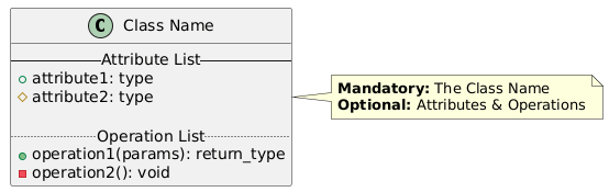
🔹 Syntax Rules
-
Name: Centered, bold, uppercase first letter.
-
Attributes:
name: type— e.g.,age: int -
Operations:
operationName(parameters): returnType— e.g.,getAge(): int
🔹 Visibility Symbols
| Symbol | Meaning | Description |
|---|---|---|
+ |
Public | Accessible everywhere |
- |
Private | Only within the class |
# |
Protected | Within class and subclasses |
🔹 Example: Person Class
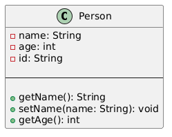
✅ In code: This maps to a
public class Personwith private fields and public getters/setters.
🔍 3. Perspectives of Class Diagrams
The level of detail and focus depends on the development phase and purpose of the model.
| Perspective | Focus | When to Use |
|---|---|---|
| Conceptual | Domain concepts (e.g., “Customer”, “Order”) | Early stages – domain modeling |
| Specification | Interfaces, abstract types, contracts | Analysis phase – define what the system does |
| Implementation | Concrete classes, method details, data types | Design & coding phase – how it’s built |
📌 Tip: Start with conceptual, evolve into implementation as you design.
🔗 4. Relationships Between Classes
UML supports five core relationships that define how classes interact. Understanding them ensures your design reflects real-world logic.
🔹 1. Inheritance (Generalization)
“Is-a” relationship
Represents inheritance, where a subclass inherits behavior and attributes from a superclass.
-
Arrow: Hollow triangle (pointing to parent class)
-
Abstract class: Italicized name (e.g., Shape)
-
Subclasses are more specific (e.g.,
Circle,Rectangle)
✅ Example: Shapes Hierarchy
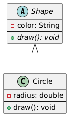
💬
Circleis aShape. It inheritsdraw()andcolor.
🧠 Use Case: Polymorphism — call
draw()on any shape without knowing its type.
🔹 2. Association
“Has-a” relationship — structural link between two classes.
-
Represented by a solid line connecting two classes.
-
Often named with a verb (e.g.,
manages,owns,interactsWith). -
Can be bidirectional or unidirectional.
✅ Example: Student and Course
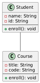
🔄 Bidirectional: A
Studentenrolls in aCourse, and aCoursehas manyStudents.
📌 Note: Association can have multiplicity (cardinality) at each end.
🔹 3. Aggregation
“Part-of” relationship — weak ownership
-
Represents loose coupling — the part can exist independently of the whole.
-
Unfilled diamond (hollow) at the whole end.
✅ Example: University and Department
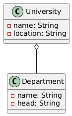
🟨 Unfilled Diamond on
Universityside →Departmentcan exist withoutUniversity.
🧩 If the university closes, departments may move elsewhere.
🔹 4. Composition
“Whole-part” relationship — strong ownership
-
The part cannot exist independently of the whole.
-
Filled diamond (solid) at the whole end.
-
When the whole is destroyed, the parts are destroyed too.
✅ Example: House and Room
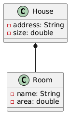
🔴 Filled Diamond on
House→Roomdies whenHouseis demolished.
🛠️ Used in composite pattern — e.g., a
DocumentcontainsParagraph,Image, etc.
🔹 5. Dependency
“Uses” relationship — temporary or indirect usage
-
Dashed line with open arrow from dependent to supplier.
-
Occurs when one class uses another in a method (e.g., as a parameter, return value, or local variable).
-
Not stored as a field → no long-term relationship.
✅ Example: Person and Book
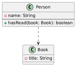
📌
PersonusesBookonly temporarily in thehasRead()method — not stored as a field.
✅ This is a dependency, not an association.
🔹 6. Realization (Interface Implementation)
“Implements” relationship
-
Connects an interface to a class that implements it.
-
Dashed line with open triangle pointing to the interface.
✅ Example: Owner Interface and Person
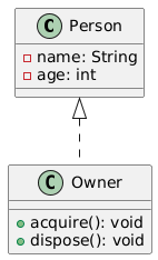
✅
Personrealizes theOwnerinterface → must implementacquire()anddispose().
💡 This is not inheritance — it’s interface implementation.
🔄 Multiple classes can realize the same interface (e.g.,
Corporationalso implementsOwner).
🧱 5. Class Diagram Example: Order System
Let’s design a simple Order Management System using UML.
📌 Entities Involved:
-
Customer -
Order -
OrderItem -
Product -
Payment
🎯 Design Goals:
-
A
Customerplaces one or moreOrders. -
Each
Ordercontains multipleOrderItems. -
Each
OrderItemrefers to aProduct. -
Each
Orderhas onePayment.
🖼️ UML Class Diagram (Text Representation)
📌 Relationships:
-
Association:
Customer→Order(1 to many) -
Composition:
Order→OrderItem(whole-part) -
Aggregation:
Order→Payment(can exist independently) -
Association:
OrderItem→Product(many-to-one)
✅ This model supports:
Creating orders
Adding items
Calculating totals
Processing payments
🖼️ 6. Class Diagram Example: GUI Application (MVC Pattern)
Let’s model a simple GUI Login Form using MVC (Model-View-Controller) architecture.
📌 Components:
-
LoginController(handles logic) -
LoginView(displays UI) -
UserModel(stores user data)
🎯 Relationships:
-
LoginControllerusesLoginViewto display data. -
LoginControllerusesUserModelto retrieve/save user info. -
LoginViewdisplays data fromUserModel.
🖼️ UML Class Diagram (Text)
🔗 Relationships:
-
Dependency:
LoginController→LoginView(uses in method) -
Dependency:
LoginController→UserModel(uses in method) -
Association:
LoginControllerhas a reference toLoginViewandUserModel(as fields)
✅ This reflects MVC: Controller mediates between View and Model.
🛠️ 7. Tools to Create UML Class Diagrams
✅ Visual Paradigm Community Edition (Free & Powerful)
-
Supports all UML diagrams
-
Intuitive drag-and-drop interface
-
AI-powered assistance for faster learning and design
🚀 Try it now: Download Visual Paradigm CE
🔧 AI-Powered Features
| Tool | Use Case |
|---|---|
| AI Class Diagram Wizard | Step-by-step class creation with AI suggestions |
| Use Case Studio | Extract classes and relationships from use case descriptions |
| Agilien | Generate class diagrams from Agile user stories |
| DB Modeler AI | Convert class diagrams into database schema |
| MVC Architecture | Generate controller and view diagrams for web apps |
🎓 Summary: Key Concepts at a Glance
| Concept | Symbol | Meaning | Example |
|---|---|---|---|
| Class | Class |
Blueprint for objects | Customer, Product |
| Inheritance | Hollow triangle | “Is-a” | Dog → Animal |
| Association | Solid line | “Has-a” | Customer → Order |
| Aggregation | Hollow diamond | “Part-of” (weak) | University → Department |
| Composition | Solid diamond | “Whole-part” (strong) | House → Room |
| Dependency | Dashed line + arrow | “Uses” | Person → Book |
| Realization | Dashed line + triangle | “Implements” | Person → Owner |
🧠 Final Tips for Success
-
Start simple: Begin with conceptual models before diving into implementation.
-
Use meaningful names:
Customer,Order,Payment— notObj1,Obj2. -
Be consistent with visibility: Use
+for public,-for private,#for protected. -
Use AI tools to validate and auto-generate diagrams from descriptions.
-
Review relationships carefully: Ask: “Can this part exist without the whole?” → If no → composition.
📚 Related Links & Resources
-
-
AI-Powered UML Class Diagram Generator by Visual Paradigm: This page details an advanced AI-assisted tool that automatically generates UML class diagrams from natural language descriptions. It is designed to significantly streamline the software design and modeling process.
-
Real-Life Case Study: Generating UML Class Diagrams with Visual Paradigm AI: A detailed case study demonstrating how an AI assistant successfully transformed textual requirements into accurate UML class diagrams for a real-world project.
-
Comprehensive Tutorial: Generate UML Class Diagrams with Visual Paradigm’s AI Assistant: This resource provides a step-by-step guide on using the online AI assistant to create precise UML class diagrams directly from plain text input.
-
Creating a UML Class Diagram for a Library System Using AI and Visual Paradigm: A practical blog post that walks through the specific process of building a class diagram for a library management system using AI modeling tools.
-
Interactive AI Chat for UML Class Diagram Generation: This interactive conversational interface allows users to generate and refine UML class diagrams through real-time natural language interaction in a browser.
-
Building a Hotel Reservation System Class Diagram with Visual Paradigm AI: A hands-on tutorial that guides users through creating a comprehensive hotel system model leveraging integrated AI capabilities.
-
Case Study: AI-Powered Textual Analysis for UML Class Diagram Generation: This study explores how AI-driven textual analysis enables the accurate and efficient generation of diagrams from unstructured requirements.
-
How AI Enhances Class Diagram Creation in Visual Paradigm: An exploration of how Visual Paradigm leverages AI to automate and improve the creation of class diagrams for faster software design.
-
Streamlining Class Diagrams with Visual Paradigm’s AI: This article explains how AI-powered tools reduce the complexity and time required to create accurate models for software projects.
-
From Problem Description to Class Diagram: AI-Powered Textual Analysis: A guide focused on exploring how AI converts natural language problem descriptions into structured class diagrams for software modeling.
-
✅ Now It’s Your Turn!
🧩 Challenge: Draw a UML class diagram for a Library Management System with:
Book,Member,Loan,LibrarianUse composition for
LoanandBookUse aggregation for
LibrarianandLibraryUse dependency for
Librarian→Book(when checking availability)
💬 Use Visual Paradigm CE or any UML tool to sketch it!
🎁 Bonus: Master UML Faster with AI
🧠 Use AI to generate, validate, and explain your class diagrams instantly.
Whether you’re a student, developer, or architect — AI makes learning UML faster, easier, and more intuitive.
🔗 Start building your first AI-assisted class diagram today!
🌟 You now have everything you need to design clean, professional, and maintainable object-oriented systems using UML Class Diagrams.
Keep practicing, keep designing, and keep coding!
✅ Happy Modeling! 🎨💻
— Your Journey into UML Mastery Starts Here


