System architecture relies heavily on understanding how components interact over time. Communication diagrams serve as a critical tool for visualizing these relationships, focusing on the flow of data between objects rather than just their static structure. Within this framework, two fundamental concepts dictate the integrity and behavior of the system: lifelines and message triggers. These elements form the backbone of any interaction analysis, ensuring that the logical sequence of events is preserved and that state changes occur predictably.
When designing complex software systems, clarity is paramount. A diagram that fails to accurately represent timing or message causality can lead to implementation errors, race conditions, or performance bottlenecks. This guide explores the mechanics of these components, providing a technical examination of how they function within a unified modeling context.
1. Understanding Lifelines: The Backbone of Time ⏳
A lifeline represents an individual participant in a communication scenario. It is not merely a vertical line on a page; it is a temporal representation of an object’s existence during the interaction. Every object participating in the system’s logic requires a lifeline to establish its presence in the sequence of events.
1.1 The Temporal Dimension
Unlike a class diagram, which describes static structure, a communication diagram with lifelines introduces the dimension of time. The top of the lifeline represents the creation or activation of the object, while the bottom represents its deactivation or destruction. This vertical axis allows analysts to trace the lifespan of a specific instance from initiation to termination.
- Creation: The moment an object is instantiated and becomes available to receive messages.
- Execution: The period during which the object is active and processing requests.
- Destruction: The point where the object ceases to exist or is no longer relevant to the current interaction flow.
1.2 Activation Bars
Within the vertical span of a lifeline, you will often see rectangular bars. These are activation bars, indicating periods where the object is actively executing an operation. They provide immediate visual feedback regarding concurrency and processing load.
- Entry Point: Where a message is received and processing begins.
- Exit Point: Where processing concludes and control is returned.
- Reentrancy: If an object calls itself, the activation bar will nest within itself, showing recursive execution.
1.3 Lifeline Visibility
Not all objects need to be visible in every interaction. A lifeline may be dormant for a portion of the diagram, only activating when a specific message is received. This selective visibility helps reduce clutter and highlights the relevant actors for a specific use case.
| Aspect | Description | Impact on Design |
|---|---|---|
| Existence | Duration the object is active | Determines resource allocation needs |
| Activation | Period of method execution | Indicates CPU or processing load |
| Destruction | End of object lifecycle | Signals memory cleanup requirements |
2. Message Triggers: Driving the Interaction 🔗
Messages are the mechanisms by which lifelines communicate. They trigger state changes, method calls, or data requests. Analyzing these triggers is essential for understanding the logic flow and dependencies within the system.
2.1 Types of Message Triggers
Not all messages function identically. The nature of the trigger dictates how the receiving object behaves. Distinguishing between synchronous and asynchronous triggers is crucial for accurate system modeling.
- Synchronous Calls: The sender waits for the receiver to complete the task before continuing. This creates a direct dependency and blocks the sender’s execution flow.
- Asynchronous Signals: The sender transmits data and continues immediately without waiting. The receiver processes the signal independently, often in a background thread or queue.
- Return Messages: These indicate the completion of a task and the passing of data back to the sender. In some notations, these are implicit, but explicit return messages clarify complex data flows.
- Self-Trigger: An object calling one of its own methods. This is common in recursion or internal state management.
2.2 Message Naming Conventions
Clarity in naming prevents ambiguity. A message name should describe the action being performed rather than the implementation details.
- Verb-Noun Structure: Use names like
calculateTotalorfetchUserto describe intent. - Avoid Implementation Details: Do not use names like
getDBConnectionunless the database access is the primary focus of the interaction. - Consistency: Maintain consistent terminology across the diagram to ensure readability for all stakeholders.
2.3 Guard Conditions
Not every message is sent unconditionally. Guard conditions add logic to the trigger, ensuring a message is only sent if specific criteria are met. These are typically denoted by square brackets within the diagram.
- Boolean Logic: Simple checks like
[if user is authenticated]. - State Checks: Verifying the current state of the object before proceeding.
- Data Validation: Ensuring input parameters meet required thresholds before transmission.
3. Analyzing the Interaction Flow 🔄
Once lifelines and messages are defined, the next step is analyzing the flow. This involves tracing the path of data and control to identify potential issues or optimizations.
3.1 Path Tracing
Start from the initiating object and follow the message chain. Ensure that every message has a corresponding receiver and that every receiver has a defined response or side effect.
- Identify Entry Points: Where does the interaction begin?
- Trace Dependencies: Which objects are required for the interaction to succeed?
- Map Return Paths: How does the result propagate back to the origin?
3.2 Concurrency Analysis
Multiple messages may be sent simultaneously to different objects. Analyzing concurrency helps identify race conditions or resource contention.
- Parallel Lifelines: Objects processing messages at the same time.
- Shared Resources: Check if concurrent objects access the same data store.
- Locking Mechanisms: Determine if synchronization primitives are needed to prevent conflicts.
3.3 Error Handling
Robust systems anticipate failure. The diagram should reflect how errors are propagated and handled.
- Exception Messages: Specific messages indicating failure states.
- Recovery Paths: Alternative lifelines or messages triggered by errors.
- Timeouts: Defining how long a sender waits before aborting a request.
4. Common Pitfalls and Optimization 🛠️
Even experienced designers encounter challenges when modeling interactions. Recognizing common mistakes early can save significant development time.
4.1 Over-Complexity
Attempting to model every possible interaction in a single diagram leads to confusion. Break down complex systems into smaller, focused diagrams.
- Focus on One Scenario: Create separate diagrams for different use cases.
- Hide Details: Use sub-diagrams to hide implementation details of complex objects.
- Iterate: Start with a high-level view and refine as needed.
4.2 Ambiguous Timing
Without clear timing indicators, it is difficult to determine if messages are sequential or parallel.
- Use Time Boxes: Clearly mark time intervals if order is critical.
- Explicit Arrows: Ensure arrows clearly show direction of flow.
- Label Ordering: Number messages to enforce strict sequencing when necessary.
4.3 Missing Return Flows
Forgetting return messages can obscure the flow of data back to the caller.
- Trace Data: Ensure the result of a calculation reaches the requester.
- State Updates: Verify that state changes are acknowledged.
- Confirmation: Include acknowledgments for critical transactions.
| Pitfall | Consequence | Mitigation Strategy |
|---|---|---|
| Over-Complexity | Confusion and maintenance issues | Decompose into smaller diagrams |
| Ambiguous Timing | Implementation logic errors | Use explicit sequencing labels |
| Missing Returns | Broken data flow | Trace data paths explicitly |
| Unbalanced Messages | Deadlocks or resource leaks | Verify send/receive pairs |
5. Advanced Scenarios and Edge Cases 🧩
Beyond standard interactions, complex systems often require handling advanced scenarios. Understanding these edge cases ensures the model remains robust under stress.
5.1 Recursion and Loops
Sometimes an object must interact with itself or a loop must be represented. This requires careful notation to avoid visual clutter.
- Recursive Calls: Represented by a message arrow looping back to the same lifeline.
- Iterative Loops: Use a frame to denote a repeated block of interaction.
- Termination Conditions: Clearly define when the recursion or loop stops to prevent infinite execution.
5.2 Nested Calls
Deep hierarchies often result in nested message calls. This can obscure the primary flow if not managed well.
- Abstraction: Replace deep chains with a single message to a higher-level interface.
- Sub-Diagrams: Move nested details to a separate diagram linked by a reference.
- Highlighting: Use visual cues to distinguish primary calls from secondary support calls.
5.3 External System Integration
Interactions often extend beyond the application boundary to external services or hardware.
- Boundary Markers: Use distinct shapes or colors to represent external entities.
- Protocol Specification: Note the communication protocol (e.g., REST, TCP) near the message label.
- Latency Considerations: Acknowledge potential delays in external responses within the timing analysis.
6. Maintaining Model Accuracy 📝
A diagram is only as good as its currency. As the system evolves, the communication diagrams must be updated to reflect changes in logic or structure.
6.1 Version Control
Treat diagrams as code. Store them in version control systems to track changes over time.
- Change Logs: Document why a message or lifeline was modified.
- Review Cycles: Include diagram updates in the standard code review process.
- Deprecation: Mark obsolete paths clearly before removing them entirely.
6.2 Stakeholder Alignment
Ensure that all teams understand the model. Discrepancies between design and implementation often stem from misinterpretation.
- Walkthroughs: Conduct regular sessions to review the diagrams with developers.
- Feedback Loops: Allow implementers to flag ambiguities in the model.
- Documentation Links: Connect diagrams to detailed technical specifications.
7. Summary of Key Takeaways ✅
Effective analysis of message triggers and lifelines requires attention to detail and a clear understanding of system dynamics. By focusing on the temporal aspect of lifelines and the causal nature of message triggers, architects can build more reliable systems.
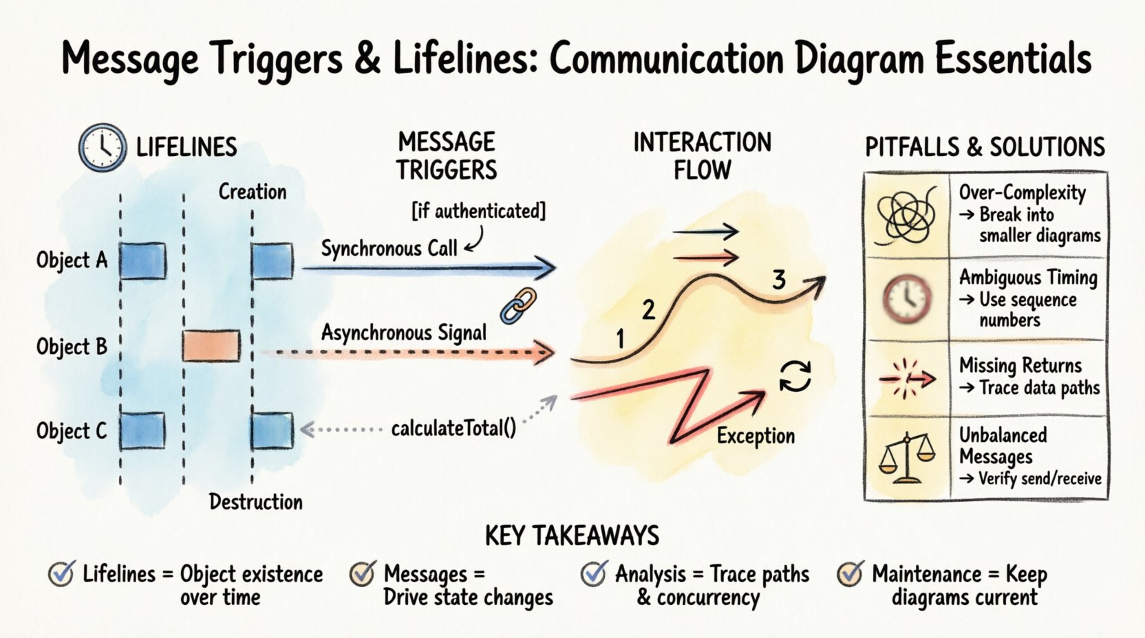
- Lifelines define the existence and activity of objects over time.
- Messages drive the interaction and state changes between participants.
- Analysis involves tracing paths, checking concurrency, and validating error handling.
- Maintenance ensures the model remains a useful asset throughout the project lifecycle.
Adopting these practices leads to clearer communication among team members and reduces the risk of architectural drift. When the interaction model is precise, the implementation follows a more predictable path, resulting in higher quality software with fewer defects.