Communication diagrams provide a structural view of interactions between objects in a system. They are essential for visualizing how data moves and how control is passed across different components. This guide details the process of creating action flows, ensuring clarity and accuracy in your system design.
🧠 Understanding Action Flows
An action flow represents the sequence of messages exchanged between objects to perform a specific function. These flows are the backbone of behavioral modeling in Unified Modeling Language (UML). They help stakeholders understand the logic behind system operations without getting bogged down in implementation details.
Key characteristics of a robust action flow include:
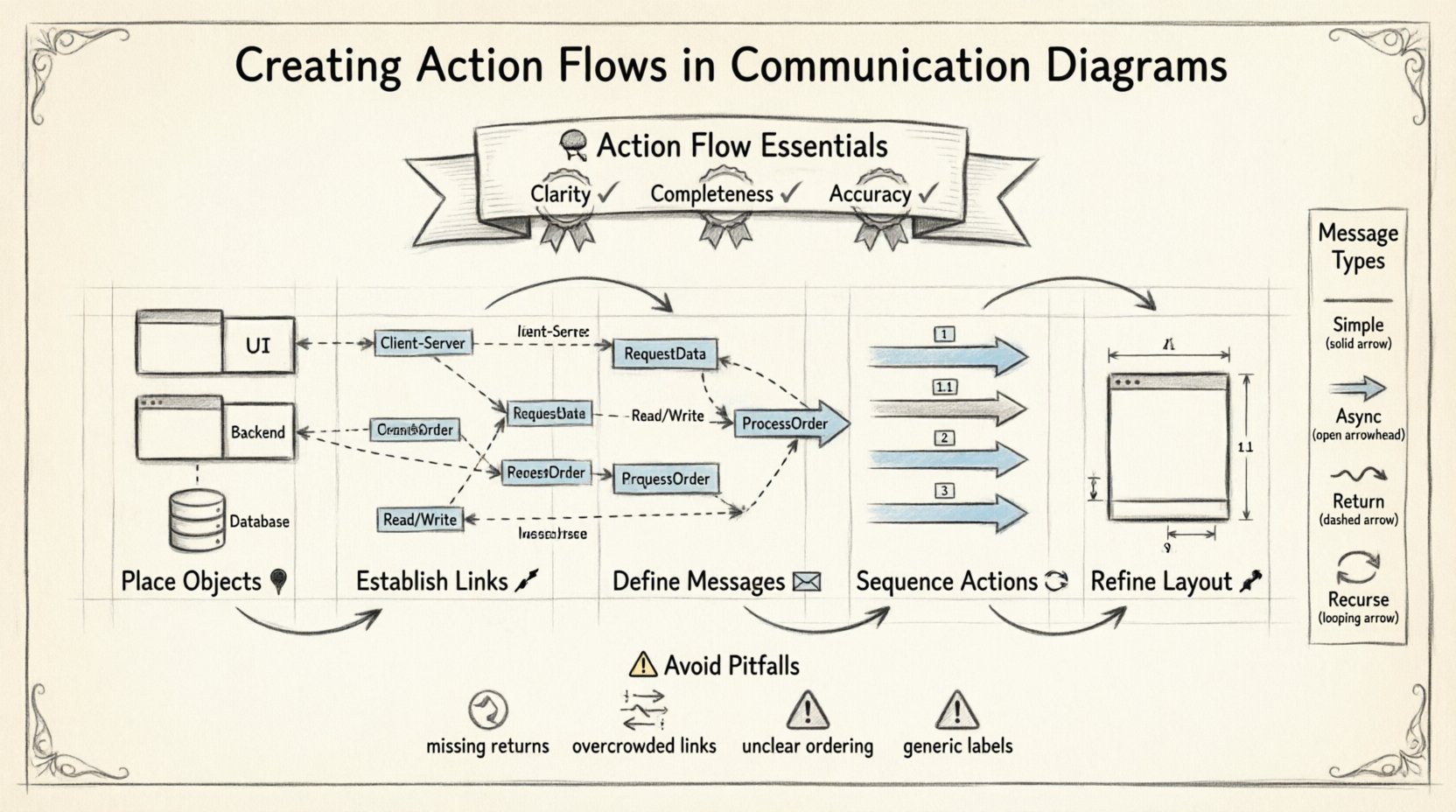
- Clarity: The path of execution should be immediately understandable.
- Completeness: All necessary interactions for the scenario must be present.
- Accuracy: The flow must reflect the actual logical sequence of events.
Unlike other diagram types, communication diagrams emphasize the static structure. This means you see the objects and their links first, with the actions overlaid upon them. This perspective is often preferred when the focus is on the architecture rather than the strict timing of events.
📋 Prerequisites for Effective Design
Before drawing a single link or message, preparation is vital. A well-structured diagram stems from a clear understanding of the system requirements and the objects involved.
1. Identify the Participants
Every interaction involves specific entities. These entities are represented as objects. You must determine which objects are active in the scenario.
- Is there a user interface component?
- Is there a backend service?
- Are there database entities involved?
2. Define the Scope
Decide what scenario you are modeling. A single diagram should not attempt to cover every possible system behavior. Focus on one specific action flow, such as “User Login” or “Data Retrieval”.
3. Gather Interface Contracts
Know what methods or operations each object exposes. This ensures that the messages you draw are valid according to the system’s design.
🛠️ Step-by-Step Creation Process
Follow this structured approach to build your communication diagram. Each step builds upon the previous one to ensure a logical progression.
Step 1: Place the Objects 📍
Begin by placing the primary objects on the canvas. These represent the actors and components participating in the flow.
- Identify the Initiator: Start with the object that triggers the action. This is often the user interface or an external system.
- Place Dependent Objects: Arrange the remaining objects based on their relationships. Group related objects together to reduce crossing lines.
- Label Clearly: Ensure every object has a unique name. Use prefixes for class names if necessary to distinguish between instances.
Step 2: Establish the Links 🔗
Links represent the connections between objects. They indicate that one object can send a message to another.
- Draw Connections: Connect objects that need to interact directly.
- Label Roles: Identify the role each end of the link plays. For example, one side might be a “Client” and the other a “Server”.
- Minimize Crossings: Arrange objects to keep links short and direct. This improves readability significantly.
Step 3: Define the Messages ✉️
Messages represent the actual action or data transfer. This is where the “action flow” comes to life.
- Arrow Direction: Draw arrows from the sender to the receiver.
- Message Naming: Use verb-based names for messages (e.g., RequestData, ProcessOrder).
- Parameters: Include key data points if they are critical to understanding the interaction.
Step 4: Sequence the Actions 🔄
Communication diagrams use numbers to indicate the order of messages. This is crucial for understanding the flow logic.
- Start with 1: The first message sent receives the number 1.
- Follow the Chain: Number subsequent messages sequentially as they occur.
- Handle Returns: Return messages can be numbered (e.g., 1.1) or marked with a dashed line, depending on the notation standard.
Step 5: Refine the Layout 🎨
Once the logic is in place, focus on the visual arrangement.
- Alignment: Align objects where possible to create a clean grid.
- Spacing: Ensure there is enough space between labels to avoid overlap.
- Consistency: Keep font sizes and line thickness uniform across the diagram.
📝 Message Types and Notations
Different types of messages convey different behaviors. Understanding these distinctions helps in creating accurate action flows.
| Message Type | Description | Notation |
|---|---|---|
| Simple | A basic call without a return value. | Solid arrow with label |
| Asynchronous | Sender does not wait for a response. | Open arrowhead |
| Return | Response from the receiver back to sender. | Dashed arrow |
| Recurse | Object calls itself. | Arrow loops back to same object |
Using the correct notation ensures that developers interpret the diagram as intended. Ambiguity in message types can lead to implementation errors.
🧩 Advanced Configurations
As your diagrams grow in complexity, you will encounter scenarios that require advanced configuration. These features allow for precise modeling of real-world logic.
1. Conditions and Guard Clauses
Not all messages happen unconditionally. You may need to show that a message is only sent if a specific condition is met.
- Label the message with a condition in brackets (e.g., [isValid]).
- Place this near the message label to keep the flow clean.
- Ensure the condition logic is documented elsewhere if complex.
2. Loops and Iterations
Sometimes an action repeats. Instead of drawing the same message multiple times, use notation to indicate repetition.
- Mark the message with an asterisk or loop notation.
- Specify the iteration count or condition if known.
- Clarify in the text if the loop is within one object or across objects.
3. Fragments and Options
Complex flows often have alternative paths. Use frames to group these optional behaviors.
- Group messages that happen under specific scenarios.
- Label the frame (e.g., Alt, Opt, Loop).
- Ensure the main flow is still visible outside the frame.
🔄 Maintenance and Updates
A communication diagram is not a one-time deliverable. Systems evolve, and diagrams must keep pace.
1. Version Control
Keep track of changes to your diagrams. If the system changes, update the diagram to reflect the new state.
- Record the date of modification.
- Note the reason for the change in the diagram legend.
- Archive older versions for reference.
2. Consistency Checks
Ensure the diagram matches the code or other design documents.
- Verify that message names match method signatures.
- Check that all objects exist in the current architecture.
- Review links to ensure no orphaned connections exist.
🚫 Common Pitfalls to Avoid
Even experienced designers make mistakes. Recognizing common errors can save time during the review process.
| Pitfall | Impact | Correction |
|---|---|---|
| Missing Return Messages | Confusion about data flow | Always include return paths for clarity |
| Overcrowded Links | Hard to trace paths | Simplify or split into multiple diagrams |
| Unclear Ordering | Logic errors in execution | Double-check message numbers |
| Generic Labels | Loss of context | Use specific method names |
🆚 Comparison: Communication vs. Sequence
It is important to know when to use a communication diagram versus a sequence diagram.
- Focus: Communication diagrams focus on object relationships. Sequence diagrams focus on time.
- Layout: Communication diagrams allow free positioning. Sequence diagrams rely on vertical timing.
- Complexity: For simple flows, communication diagrams are often cleaner. For complex timing, sequence diagrams are better.
Choosing the right tool depends on the information you need to convey to your audience. If the team needs to understand the architecture, choose communication. If they need to understand the timing, choose sequence.
📈 Best Practices for Clarity
To ensure your diagrams are effective, adhere to these guidelines.
1. Limit Scope per Diagram
Do not try to show the entire system in one view. Break complex systems into smaller, manageable flows.
- Create a separate diagram for each major use case.
- Link diagrams together if they share objects.
- Use a legend to explain common symbols.
2. Standardize Naming Conventions
Consistency reduces cognitive load for readers.
- Use camelCase for object names.
- Use PascalCase for class names.
- Keep message names short and descriptive.
3. Use White Space Wisely
Don’t cram everything together.
- Leave space around complex clusters.
- Use lines to separate distinct sections if necessary.
- Ensure labels do not overlap with arrows.
🔍 Troubleshooting Common Issues
When reviewing your work, you may encounter issues that require adjustment.
Issue: Circular Dependencies
If Object A calls Object B, and Object B calls Object A, it creates a cycle.
- Check if this is intentional (e.g., state machines).
- If unintentional, refactor the design to break the cycle.
- Use a different diagram type to clarify the loop.
Issue: Unclear Object Roles
Readers may not understand what an object does.
- Add a brief description in the legend.
- Group objects by their functional role (e.g., UI, Logic, Data).
- Ensure the initiator is clearly marked.
🏁 Final Thoughts
Creating action flows in communication diagrams is a skill that improves with practice. It requires a balance of technical accuracy and visual clarity. By following these steps and adhering to best practices, you can produce diagrams that effectively communicate system behavior.
Remember that the goal is not just to draw lines, but to facilitate understanding. A good diagram reduces the need for lengthy explanations and aligns the team on the system’s logic. Take the time to review your work from a fresh perspective, and refine until the flow is self-evident.
With consistent application of these principles, your diagrams will become reliable assets for development, documentation, and maintenance throughout the lifecycle of your software projects.