


Introduction to Sequence Diagrams
In the realm of software engineering and system design, understanding how objects interact over time is crucial for building robust applications. A UML Sequence Diagram is a specific type of interaction diagram that details exactly how operations are carried out. Unlike static models that show class structures, sequence diagrams are dynamic; they capture the interaction between objects in the context of a collaboration, focusing heavily on the order of events.
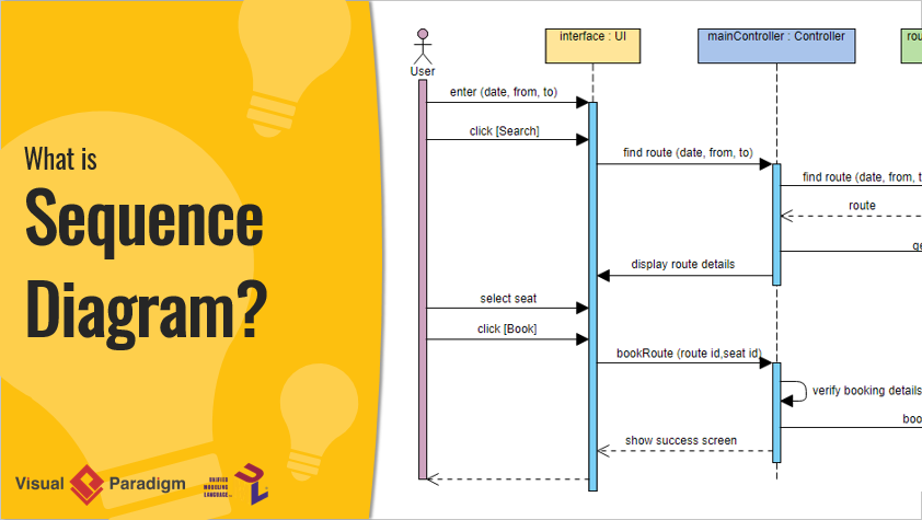
Sequence diagrams are time-focused. They visually represent the order of interactions by using the vertical axis to represent the passage of time and the horizontal axis to represent the objects involved. Whether you are modeling high-level interactions between a user and a system, or granular interactions between subsystems, these diagrams provide a blueprint for the logic flow of a scenario.
Key Concepts
Before diving into complex logic, it is essential to understand the foundational elements that make up a sequence diagram. Mastering these terms will help you interpret and construct accurate diagrams.
- Lifeline: A lifeline represents an individual participant in an interaction. Visually, it appears as a dashed vertical line extending downward from an object or actor. It indicates that the object exists during that portion of the interaction.
- Actor: An actor is a type of role played by an entity that interacts with the subject, such as a human user, external hardware, or another system. Actors are external to the subject being modeled.
- Activations: Represented by a thin rectangle on a lifeline, an activation (or focus of control) indicates the period during which an element is performing an operation. The top aligns with the initiation time, and the bottom aligns with the completion time.
- Time Dimension: The vertical axis represents time progressing down the page. It is important to note that the vertical space usually represents the ordering of events rather than specific duration, although duration constraints can be added.
- Object Dimension: The horizontal axis lists the elements involved in the interaction. Conventionally, objects are listed from left to right based on when they initiate or participate in the message sequence.
Sequence Diagram Notation and Messages
Communication in a sequence diagram is depicted through messages. A message defines a particular communication between lifelines. The type of arrow and line style changes based on the message type.

Types of Messages
- Call Message: Represents an invocation of an operation on a target lifeline. It is the primary method of passing control.
- Return Message: Represents the passing of information back to the caller of a previous message, signaling the end of an activation.
- Self Message: Represents a lifeline calling an operation on itself.
- Recursive Message: A specific type of self-message where the target points to an activation on top of the activation where the message was invoked.
- Create Message: Represents the instantiation of a new lifeline (object) during the execution of the scenario.
- Destroy Message: Represents a request to terminate the lifecycle of a target lifeline.
- Duration Message: Shows the distance between two time instants, specifically highlighting timing constraints.
Handling Complex Logic with Sequence Fragments
UML 2.0 introduced sequence fragments (or interaction fragments) to handle complex control flows such as loops, branches, and parallel processing. A fragment is represented as a box enclosing a portion of the interactions, with an operator in the top-left corner indicating its type.
Common Fragment Operators
| Operator | Description |
|---|---|
| alt | Alternative multiple fragments. Similar to an if/else statement, only the fragment whose condition is true will execute. |
| opt | Optional. The fragment executes only if the supplied condition is true. Equivalent to a single branch if statement. |
| loop | The fragment executes multiple times based on a guard condition (iteration). |
| par | Parallel. Each fragment within the box runs simultaneously. |
| break | Used to break out of the enclosing loop or flow if a condition is met. |
| ref | Reference. Refers to an interaction defined in another diagram, allowing for modularity and reuse. |
Tips and Tricks
Creating effective sequence diagrams requires balancing detail with clarity. Here are practical tips and optimizations to improve your modeling workflow.
1. Model Before You Code
While sequence diagrams can look like code logic, they should remain a level above the actual implementation. Use them to validate logic, UX wireflows, or architectural decisions before committing to code. Because they are language-neutral, they serve as excellent communication tools for non-coders and cross-functional teams.
2. Leverage Keyboard Shortcuts
If you are using tools like Visual Paradigm, mastering keyboard shortcuts can significantly speed up the drawing process. Instead of dragging and dropping, use the Quick Editor hotkeys:
- Alt-Shift-A: Create an Actor
- Alt-Shift-L: Create a general Lifeline
- Alt-Shift-E: Create an Entity Lifeline
- Alt-Shift-C: Create a Control Lifeline
- Alt-Shift-B: Create a Boundary Lifeline
3. Use AI for Rapid Prototyping
Modern modeling tools have integrated AI to streamline diagram generation. Features like Visual Paradigm’s AI Diagram Generation allow you to type a description of a scenario (e.g., “An ATM System” or “Online Learning Platform”) and automatically generate a structured sequence diagram. This provides a perfect starting point that is perfectly laid out and ready to refine, saving hours of manual formatting.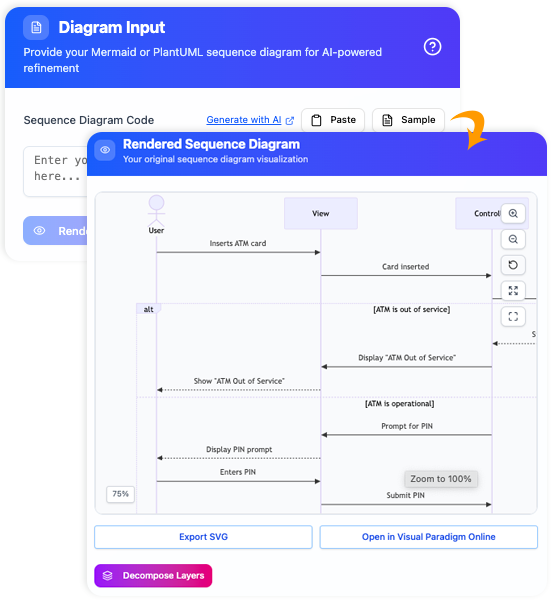
4. Focus on Ordering, Not Duration
Remember that the vertical space primarily signifies the sequence of events. Unless you are modeling a real-time system with strict latency requirements, do not worry about the exact pixel distance between messages. Focus on who sends what message and in what order.
5. Utilize ‘Ref’ for Readability
If a diagram becomes too long or complex, break it down using the ref fragment. This allows you to reference another sequence diagram, keeping the main view high-level and readable while encapsulating details in separate files.