


Introduction to Modern Systems Engineering
In the realm of complex systems engineering, clarity and precision are paramount. As projects scale to include intricate combinations of software, hardware, information, and processes, standard modeling practices become essential. This guide explores the System Modeling Language (SysML), its practical application through Visual Paradigm, and how artificial intelligence is revolutionizing the diagramming process.
Understanding SysML: The Language of Systems
System Modeling Language (SysML) is a general-purpose graphical modeling language for specifying, analyzing, designing, and verifying complex systems. Developed as an extension of the Unified Modeling Language (UML) by the Object Management Group (OMG) in collaboration with INCOSE, SysML is designed to capture both functional and physical aspects of a system.
While UML is dominant in software development, SysML addresses the broader needs of systems engineering. It allows engineers to model the interactions between hardware and software components, ensuring a holistic view of the system architecture. By providing a standard set of constructs, SysML acts as a common language, facilitating communication among diverse engineering teams and stakeholders.
SysML vs. UML
Although based on UML, SysML is a more streamlined language tailored for systems engineering. It reduces the complexity of UML by including only the elements relevant to systems modeling while adding new constructs for requirements, constraints, and parametrics. specifically, SysML utilizes nine diagram types compared to UML’s fourteen, removing software-centric elements that are not useful in a broader systems context.
The Three Pillars of SysML Diagrams
SysML diagrams are categorized into three major groups: Structure, Behavior, and Requirements. Understanding these categories is essential for effective Model-Based Systems Engineering (MBSE).
1. Structure Diagrams
Structure diagrams define the physical or logical architecture of the system. They answer the question: “What is this system made of?”
- Block Definition Diagram (BDD): This is the foundation of system hierarchy. It defines the system and component classifications (blocks) and illustrates the relationships and interconnections between them. It is used to visualize the static structure of the system.
- Internal Block Diagram (IBD): While BDDs show hierarchy, IBDs look inside a specific block. They describe the internal structure in terms of parts, ports, and connectors, detailing how the parts of a block interact with each other.
- Package Diagram: Essential for model management, this diagram organizes model elements into packages, showing dependencies and containment hierarchies.
2. Behavior Diagrams
Behavior diagrams illustrate the dynamic aspects of the system. They answer the question: “What does this system do?”
- Activity Diagram: Focuses on the flow of control and transformation of inputs to outputs. It is used to specify desired behaviors for features or use cases.
- Sequence Diagram: details the interaction between parts of a block via operation calls and asynchronous signals over time. It is effectively a storyboard for system operations.
- State Machine Diagram: Depicts the lifecycle of a block, showing the transitions between different states in response to events. This is crucial for simulation and code generation.
- Use Case Diagram: A black-box view of the system that captures functional requirements as transactions meaningful to users (actors).
3. Requirement and Parametric Diagrams
SysML introduces specialized diagrams to handle engineering constraints and requirements.
- Requirement Diagram: Provides a visual approach to representing, managing, and tracing system requirements. Requirements are shown as blocks with connectors illustrating derivation, dependency, and grouping.
- Parametric Diagram: A restricted form of the Internal Block Diagram, this tool represents constraints on system properties (such as performance, reliability, and mass) to support engineering analysis.
Leveraging Visual Paradigm for SysML
Visual Paradigm offers a robust environment for creating industry-standard SysML diagrams. It bridges the gap between theoretical modeling and practical application with features designed for professional engineers.
Key Features for Systems Engineers
The platform supports the full lifecycle of system design:
- Requirement Management: The tool allows users to define custom requirement types with user-defined properties. It includes functionality to export requirement lists to Excel for external manipulation and import them back for updates, ensuring data integrity.
- Desktop and Cloud Integration: Visual Paradigm operates as both a desktop application and a cloud-based service (VP Online). This hybrid approach allows for seamless transitions between offline modeling and online collaboration.
- Traceability: Users can establish traceability between features (use case models) and behavior models (activity diagrams), ensuring that every design element serves a specific requirement.
Accelerating Modeling with AI Chatbots
The traditional process of drawing diagrams manually is being transformed by Artificial Intelligence. Visual Paradigm has integrated an AI Chatbot directly into its platform, allowing for instant diagram generation through natural language processing.
From Text to Diagram
The AI Chatbot acts as a conversational interface for visual modeling. Instead of dragging and dropping shapes, users can simply describe their intent. The workflow involves four simple steps: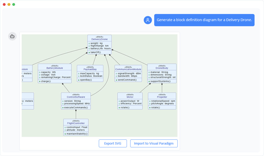
- Describe Your Idea: Type a prompt such as “Create a SysML Block Definition Diagram for an autonomous vehicle.”
- Generate Instantly: The AI analyzes the intent and generates a complete, presentation-ready diagram in seconds.
- Refine with Commands: Users can modify the output using natural language commands like “Add a power supply block” or “Rename Controller to Main Processor.”
- Explore and Document: The AI can also analyze the diagram to generate project summaries or answer questions about the system structure.
Supported Diagrams and Integration
The AI diagram generator supports a vast array of diagram types, including SysML Block Definition Diagrams, Requirement Diagrams, and Internal Block Diagrams, as well as standard UML and business strategy frameworks like SWOT and PESTLE analysis.
Crucially, this feature is integrated with the desktop environment. Users with a Professional Edition license can generate diagrams via the AI Chatbot on the web and import them directly into their Visual Paradigm Desktop projects for further detailed modeling and refinement. This synchronization ensures that the speed of AI does not compromise the depth of professional engineering tools.