


In the landscape of software development, clarity is currency. When teams collaborate, they need a shared language to describe complex systems. Class diagrams provide that syntax. They are not just drawings; they are contracts. They define the structure, behavior, and relationships that drive a system forward. However, a diagram that is too dense becomes noise. A diagram that is too simple becomes useless. The art lies in the balance.
Designing intuitive class diagrams requires a deep understanding of Object-Oriented Analysis and Design (OOAD). It demands that you see beyond the code and visualize the domain. This guide explores the methodology for creating diagrams that communicate effectively, reduce cognitive load, and serve as reliable documentation throughout the software lifecycle.
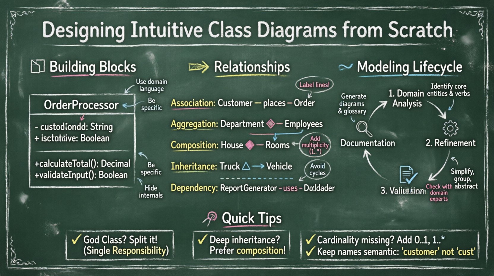
🧱 Understanding the Building Blocks
Before drawing lines between boxes, you must understand what constitutes a box. A class is the fundamental unit of structure. It encapsulates data and logic. To make a diagram intuitive, every element must have a clear purpose.
1. The Class Name
The name is the most critical identifier. It should be a noun, representing a concept in the domain. Avoid generic names like Manager or Data. Instead, use specific terms like OrderProcessor or CustomerRecord.
- Consistency: Ensure naming conventions are consistent across the entire diagram.
- Domain Language: Use the vocabulary of the business. If the business calls it a
Subscription, do not name itAccountunless there is a technical reason. - Capitalization: Follow standard conventions, typically PascalCase for classes.
2. Attributes (Data)
Attributes represent the state of the class. In a diagram, these are the properties stored within the object.
- Visibility: Use symbols to denote access levels.
+for public,-for private, and#for protected. - Type: Always specify the data type (e.g.,
String,Integer,Date). - Minimality: Do not list every single internal variable. Only include attributes relevant to the current level of abstraction.
3. Methods (Behaviors)
Methods represent actions. They define what the class can do.
- Verbs: Names should be action-oriented (e.g.,
calculateTotal,validateInput). - Parameters: Show input parameters in parentheses.
- Return Types: Indicate what the method returns.
- Abstraction: Hide implementation details. If a method is internal, consider using visibility modifiers to keep the diagram clean.
🔗 Mapping Relationships and Dependencies
Classes do not exist in isolation. They interact. The lines connecting them tell the story of how data flows and how responsibilities are shared. Misinterpreting these lines leads to architectural flaws.
The following table outlines the standard relationship types used in Object-Oriented Analysis and Design.
| Relationship Type | Symbol | Description | Example |
|---|---|---|---|
| Association | Solid Line | A structural link where objects know about each other. | A Customer places an Order. |
| Aggregation | Open Diamond | A “has-a” relationship where parts can exist independently. | A Department has Employees. Employees exist without the department. |
| Composition | Filled Diamond | A strong “has-a” relationship. Parts cannot exist without the whole. | A House contains Rooms. If the house is destroyed, rooms cease to exist. |
| Inheritance | Open Triangle Arrow | An “is-a” relationship. Subclasses inherit properties. | Truck extends Vehicle. |
| Dependency | Dashed Line | A usage relationship. One class depends on another for a task. | A ReportGenerator uses a DataLoader. |
Best Practices for Relationships
- Label the Lines: Always name the relationship if it has a specific meaning (e.g., “owns”, “contains”, “uses”).
- Multiplicity: Indicate how many objects are involved (e.g., 1..*, 0..1). This clarifies cardinality constraints.
- Avoid Cycles: Circular dependencies create tight coupling. Review cycles to ensure they are intentional and manageable.
📝 Naming for Clarity and Readability
A diagram is a visual document. If the reader has to squint to understand a label, the design has failed. Naming conventions are not just style rules; they are cognitive aids.
1. Readability Hierarchy
When scanning a diagram, the eye should follow a logical path.
- Font Size: Keep class names prominent. Attribute and method text should be smaller.
- Grouping: Use packages or frames to group related classes. This reduces visual noise.
- Spacing: Allow whitespace between unrelated classes. Clustering should reflect domain logic, not just screen real estate.
2. Semantic Naming
Avoid abbreviations unless they are industry-standard. Instead of cust, use customer. Instead of inv, use invoice.
- Context Matters: A
Userin a social app might differ from aUserin a banking app. Be specific. - Verb Consistency: If you use
getprefixes, use them consistently across the diagram.
🔄 The Modeling Lifecycle
Designing a class diagram is not a one-time event. It is an iterative process that evolves with the requirements.
Phase 1: Domain Analysis
Start with the problem space. Identify the key entities. Do not worry about code yet. Focus on nouns found in the requirements documentation.
- List all potential entities.
- Identify which are core and which are peripheral.
- Draw rough sketches of connections.
Phase 2: Refinement
Transform entities into classes. Define attributes and methods.
- Check for Single Responsibility Principle. If a class does too much, split it.
- Define interfaces for abstract behaviors.
- Establish the primary relationships (Association, Inheritance).
Phase 3: Validation
Review the diagram with stakeholders and developers.
- Does the diagram match the business rules?
- Are the relationships technically feasible?
- Is the level of detail appropriate for the audience?
Phase 4: Documentation
Finalize the diagram for version control. Ensure it is linked to the corresponding codebase.
- Include a legend for any custom symbols.
- Document the version and date of the diagram.
- Link to the relevant requirement tickets.
🛡️ Managing Complexity and Abstraction
As systems grow, diagrams become overwhelming. You must manage complexity through abstraction levels. A single diagram cannot show everything.
1. Layering
Create different diagrams for different purposes.
- High-Level Overview: Show major subsystems and their connections.
- Domain Model: Focus on business entities and their relationships.
- Implementation Model: Show technical details, including interfaces and concrete classes.
2. Interfaces and Abstract Classes
Use interfaces to define contracts without revealing implementation.
- Draw the interface as a separate box with a stereotype.
- Connect implementing classes with a dashed line and an open triangle.
- This allows you to swap implementations without changing the diagram’s structure.
3. Hiding Internal Details
Do not clutter the main diagram with every private variable. If a class contains a complex sub-structure, consider creating a separate diagram for that component.
- Use composition to group related functionality.
- Hide internal helper classes unless they are critical to the design.
🚫 Common Pitfalls and How to Avoid Them
Even experienced architects make mistakes. Being aware of common anti-patterns helps you maintain high-quality diagrams.
1. The God Class
One class that knows everything is a design smell. It creates tight coupling and makes testing difficult.
- Sign: The class has an excessive number of attributes and methods.
- Fix: Delegate responsibilities to other classes. Use the Single Responsibility Principle.
2. Deep Inheritance Hierarchies
Too many levels of inheritance make the system brittle and hard to understand.
- Sign: Classes nested five or more levels deep.
- Fix: Prefer composition over inheritance. Use interfaces where appropriate.
3. Ignoring Cardinality
Failing to specify how many objects are involved leads to ambiguity.
- Sign: Lines connecting classes without multiplicity labels.
- Fix: Explicitly define 1, 0..1, 1..*, or 0..* on all association ends.
4. Inconsistent Notation
Using different symbols for the same concept confuses readers.
- Sign: Mixing standard UML symbols with proprietary icons.
- Fix: Adhere to standard notation guidelines. Define a style guide for the team.
🔄 Maintenance and Evolution
A class diagram that is not maintained becomes a liability. It misleads developers and slows down onboarding. Treat the diagram as living documentation.
1. Synchronization
Ensure the diagram reflects the actual code. If a class is refactored, update the diagram immediately.
- Integrate diagram updates into the code review process.
- Automate generation where possible to reduce manual errors.
- Set a deadline for reviewing diagrams during sprint planning.
2. Versioning
Track changes over time. This helps in understanding why a specific design decision was made.
- Keep a history of diagram versions.
- Document the rationale for major structural changes.
- Archive old diagrams rather than deleting them.
3. Feedback Loops
Encourage feedback from the team. Developers who write the code often spot issues in the diagram.
- Hold design review sessions focused on the diagrams.
- Ask new team members to interpret the diagram; if they struggle, simplify it.
- Use the diagram as a training tool for onboarding.
🔍 Aligning with Business Requirements
The ultimate goal of a class diagram is to support the business logic. It must bridge the gap between technical implementation and business value.
1. Domain-Driven Design
Align your classes with the ubiquitous language of the business.
- Ensure every class maps to a business concept.
- Remove technical classes that do not serve the domain model directly.
- Group classes into Bounded Contexts to manage scope.
2. Validation of Constraints
Business rules often dictate constraints on the model.
- If a business rule states an
Ordermust have at least oneItem, enforce this in the multiplicity (1..*). - If a
Usermust be active to place an order, represent this state in the class attributes or methods. - Document these constraints in the diagram notes or legends.
3. Scalability Considerations
Design with future growth in mind, but avoid premature optimization.
- Identify areas that are likely to change frequently.
- Use interfaces to decouple these areas from the core logic.
- Plan for horizontal scaling by ensuring stateless design where applicable.
🎯 Final Thoughts on Visual Communication
Creating a class diagram is an exercise in empathy. You are designing for the person who will read it next. Whether it is a new developer joining the team or a senior architect reviewing the system, the diagram must speak clearly.
Focus on the essentials. Strip away the unnecessary. Use standard conventions. Validate your assumptions. A well-designed diagram reduces risk, accelerates development, and improves collaboration. It transforms abstract requirements into a concrete blueprint that guides the construction of robust software systems.
Remember, the diagram is a tool, not the goal. The goal is a maintainable, scalable, and understandable system. Let the diagram serve that purpose by remaining clear, accurate, and up to date.