


Introduction to UML Component Diagrams
In the complex world of software engineering, understanding how different parts of a system interact is crucial. A Component Diagram is one of the 14 fundamental diagram types defined in UML 2.5. It falls under the category of structural diagrams and is specifically designed to visualize the organization and wiring of physical or logical components within a system.
These diagrams are essential for answering critical architectural questions, such as:
- What are the major replaceable or reusable pieces of the system?
- How do these pieces depend on one another?
- Which interfaces do specific components provide, and which do they require?
- How is the software mapped to actual deployment artifacts like JARs, DLLs, or executables?
Component diagrams differ from class diagrams by focusing on higher-level abstractions. They are particularly valuable for documenting large-scale enterprise systems, component-based architectures (such as SOA, microservices, or OSGi), and packaging structures like Maven modules or Docker images.
Step 1: Mastering Key Concepts and Notation
To create an effective diagram, you must first understand the standard notation. Below is a breakdown of the primary symbols used in component diagrams.
| Symbol Name | Meaning | Visual Representation |
|---|---|---|
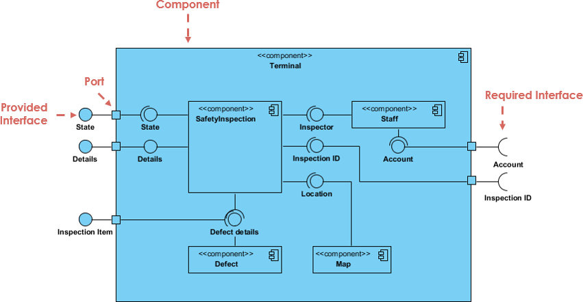
| Component | A modular, replaceable part of a system that encapsulates implementation and exposes interfaces. | A rectangle labeled with the keyword «component» or the component icon (two small rectangles on the left side). |
| Provided Interface | Functionality the component offers to other components. | Represented by a circle or “ball” on the component border (often called a lollipop). |
| Required Interface | Functionality the component needs from external sources to function. | Represented by a half-circle or “socket” on the component border. |
| Port | A specific interaction point on a component, often used to group interfaces. | A small square on the component border. |
| Assembly Connector | The wiring that connects a required interface (socket) to a provided interface (lollipop). | A line connecting the socket and ball. |
| Delegation Connector | Connects a port on the outer boundary of a component to its internal implementations. | A line from an outer port to an internal part or interface. |
| Dependency | Indicates that one component uses another (coarser than an interface connection). | A dashed arrow pointing to the dependency. |
| Artifact | A physical file or deployment unit (e.g., JAR, WAR, DLL). | A rectangle labeled with the keyword «artifact». |
Step 2: Defining Interfaces
The core power of a component diagram lies in its ability to decouple implementation from usage through interfaces. There are two distinct types of interfaces you need to model:
Provided Interfaces (The Lollipop)
A provided interface represents a contract that the component fulfills. It is the service the component offers to the rest of the system. Visually, this is depicted as a complete circle (ball) attached to the component via a solid line.

Required Interfaces (The Socket)
A required interface represents a dependency. It specifies what the component needs to do its job. Visually, this is a semi-circle (socket) attached to the component.
When you connect a socket from one component to the lollipop of another, you create an Assembly Connector. This signifies that the requirement of the first component is satisfied by the functionality provided by the second.
Step 3: utilizing Ports and Internal Structure
For complex systems, specifically in microservices or layered architectures, components may have internal structures or specific interaction points known as Ports.
Using Ports
Ports are small squares on the boundary of a component. They are useful when a component has multiple distinct roles or interfaces that need to be grouped logically. For example, an OrderService might have one port for public API requests and a different port for administrative monitoring tools.
Internal Composite Structure
You can “open up” a component to show its internal wiring. This is known as a composite structure. For instance, a high-level PaymentService component might internally contain an OrderProcessor, a PaymentClient, and an AuditLogger. These internal parts can be connected using delegation connectors, showing how external requests are routed to internal logic.
Step 4: Mapping to Artifacts and Deployment
While components represent logical units, Artifacts represent the physical files that are deployed. A manifest relationship shows how components are packaged.
For example, you might have a logical component called OrderService. In the physical world, this might be packaged into a file called order-service.jar. You visualize this relationship using a dashed arrow labeled «manifest» pointing from the Artifact to the Component.
Step 5: Real-World Use Cases
Component diagrams are versatile. Here are common scenarios where they excel:
- Microservices Architecture: Modeling each service as a component and defining REST or gRPC endpoints as interfaces.
- Third-Party Integration: clearly showing required interfaces that connect to external systems like Stripe or SAP.
- Legacy Modernization: Documenting old DLLs or libraries to understand dependencies before refactoring.
- CI/CD Planning: Mapping logical components to Docker images or NuGet packages to verify deployment strategies.
Step 6: Best Practices for Effective Diagrams
To ensure your component diagrams are readable and useful, follow these best practices:
- Scope Appropriately: Do not try to model the entire enterprise in one diagram. Create separate diagrams for specific subsystems.
- Prioritize Interfaces: The value of this diagram is in showing contracts. Ensure you clearly distinguish between provided and required interfaces.
- Use Stereotypes: Use labels like «service», «database», or «facade» to clarify the nature of the component.
- Avoid Spaghetti: Only show critical dependencies. If every component depends on a utility library, you usually don’t need to draw a line from every component to that library; it clutters the view.
- Consistency: Stick to one icon style (either the stereotype text or the component icon) throughout the diagram.
Conclusion
Component diagrams bridge the gap between high-level architectural intent and low-level class design. By clearly defining boundaries, dependencies, and interfaces, they serve as a blueprint for implementation and a map for deployment. Whether you are building a monolithic application with distinct modules or a distributed microservices network, mastering the component diagram is an essential skill for modern software architects.
The following articles and tutorials provide information on creating and utilizing UML component diagrams, including those enhanced by AI, within the Visual Paradigm environment:
-
Major Upgrade to AI UML Component Diagram Generation in Visual Paradigm AI Chatbot: The Visual Paradigm AI Chatbot now features advanced capabilities for generating detailed UML component diagrams directly from natural language prompts.
-
AI-Powered Component Diagrams with Visual Paradigm Chatbot: This tool simplifies the modeling process by transforming descriptive text into precise, ready-to-use component diagrams.
-
AI-Generated UML Component Diagrams: This article explores how artificial intelligence assistance enables the accurate and efficient creation of component diagrams for modern software design.
-
UML Component Diagram Tutorial and Tool – Visual Paradigm: This resource provides an interactive guide for modeling system architecture and visualizing various component relationships.
-
Component Diagram Software – Visual Paradigm Online: Teams can design detailed software component models using a powerful online tool that supports UML standards and real-time collaboration.
-
Free UML Editor Online – Visual Paradigm: This web-based editor allows users to create professional class, sequence, and component diagrams without requiring a software installation.
-
Why Every Team Needs an AI Diagram Maker for Faster Project Kickoff: This post highlights how AI-powered tools accelerate the initial stages of a project by automating the generation of UML and component diagrams.
-
UML Component Diagram Tutorial: Designing Software Architecture: This video tutorial offers a step-by-step guide for modeling software modularity and dependencies through UML component diagrams.
-
UML Component Diagram Tutorial: Building Modular Software Systems: This guide provides clear instructions on creating component diagrams to represent the internal modular structure of a software system.
-
Comprehensive UML Component Diagram Guide: This tutorial provides an in-depth walkthrough for creating component diagrams to model modularity in complex software architectures.