


Bridging Structure and Behavior in Software Architecture
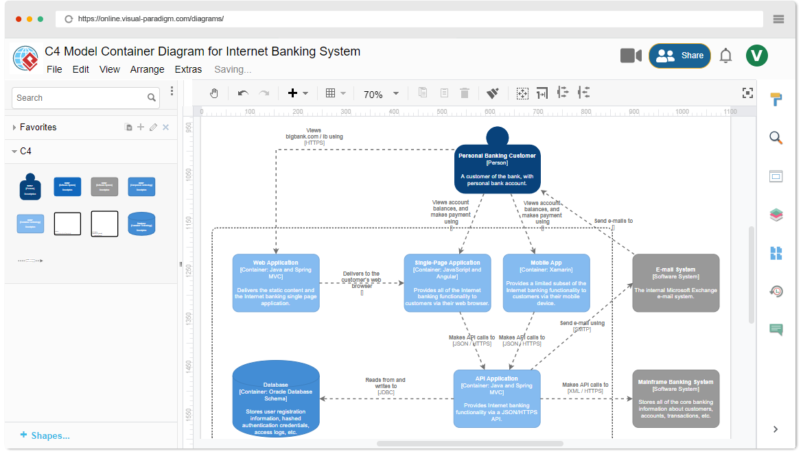
In modern software engineering, communicating architecture effectively is just as critical as the code itself. The C4 model has emerged as a standard for visualizing software architecture, organizing systems into four hierarchical levels of abstraction: Context, Containers, Components, and Code. This hierarchical approach excels at visualizing the static structure of a system—showing what exists and how different parts are connected.
However, static structure is only half the picture. Complex systems often require a clear definition of the behavioral dimension—the specific logic governing how components react to inputs over time. To address this, architects integrate UML state diagrams within the C4 framework. This guide explores the synergy between structural C4 models and behavioral state diagrams, detailing when, why, and how to implement them effectively using Visual Paradigm.
The Intersection of C4 and State Diagrams
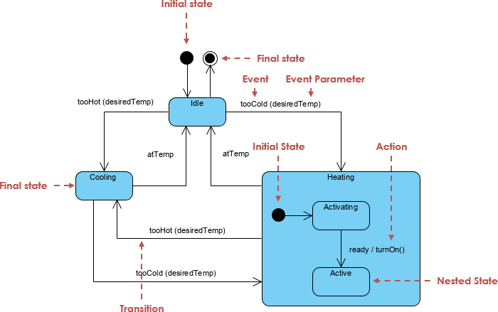
While the C4 model provides a map of the software landscape, it does not inherently describe the rules of the road. State diagrams fill this void by modeling the lifecycle of objects and components.
When to Use State Diagrams in C4 Architecture
State diagrams are not necessary for every level of the C4 model. They are most effective when applied at the granular end of the hierarchy:
- Component Level (Level 3): At this stage, state diagrams model the internal logic of specific components that manage complex lifecycles. For example, within a “Payment Processor” container, a state diagram can visualize the transition of a transaction from Initiated to Authorized, Captured, or Failed.
- Code Level (Level 4): Here, state diagrams are applied to individual class instances. They visualize how a specific object responds to internal or external events, ensuring that the code implementation aligns perfectly with the intended architectural logic.
Why Integrate State Diagrams with C4?
Combining these two modeling techniques offers distinct advantages for developers and architects dealing with complex systems.
Modeling Logic Over Structure
C4 diagrams focus primarily on the “what”—the existence of elements and their relationships. In contrast, state diagrams explain the “how”. They detail the behavior of an element when it receives specific inputs, providing a dynamic view that static diagrams cannot convey.
Handling Complex Operational States
Certain systems are defined by their states rather than their data flow. Systems with critical operational logic, such as 3D printers, automated toll systems, or embedded medical devices, require state diagrams to map every possible transition. This rigor helps architects avoid fatal design errors in state-dependent behavior, such as a machine attempting to print while the door is open.
Ensuring Design Consistency
Using state diagrams alongside C4 models acts as a validation mechanism. It allows developers to identify missing or undefined behavioral paths early in the design phase. By visualizing the transition rules, teams can ensure that the component interactions defined in the C4 diagrams are actually feasible given the object’s internal logic.
Implementing the Workflow with Visual Paradigm
Visual Paradigm provides a comprehensive ecosystem that leverages AI to bridge the gap between structural C4 modeling and behavioral state definition. Below is a step-by-step workflow for implementing this integration.
1. Generate Structural Architecture
The process begins by establishing the static foundation. Users can utilize the AI Diagram Generator or C4-PlantUML Studio to transform natural language descriptions into layered C4 diagrams. This creates the structural skeleton of the system, identifying the Context, Containers, and Components.
2. Define Behavioral Logic with AI
Once the components are identified, the focus shifts to behavior. Using the Visual Paradigm AI Chatbot, architects can generate a corresponding UML state machine diagram simply by providing a text prompt describing the system’s logic. This drastically reduces the manual effort required to draft complex transitions.
3. Ensure Modeling Continuity
A major challenge in architecture is keeping different diagrams in sync. The Visual Paradigm platform supports modeling continuity, enabling designers to link structural C4 elements directly to the behavioral state diagrams. This creates a navigable model where clicking a component in a C4 diagram can reveal its internal state logic.
4. Refine Transitions and Actions
AI generation provides a solid baseline, but precise logic requires human expertise. Using the Interactive State Machine Diagram Tool, teams can collaboratively define and edit Entry, Exit, and Do activities for each state. This step is crucial for ensuring that the logic handles edge cases and specific business rules accurately.
5. Automate Implementation
The ultimate goal of modeling is implementation. After the behavioral model is finalized, the platform offers instant code generation from the state diagrams. This allows for a seamless transition from the “Code” level of the C4 architecture directly to functional source code, minimizing the risk of translation errors between design and development.
6. Maintain Traceability
Software evolves, and architecture must keep up. Visual Paradigm’s impact analysis tools allow users to trace how changes in a high-level C4 container might ripple down to affect the state transitions of underlying components. This ensures that the entire architectural design remains aligned and consistent throughout the project lifecycle.
The following articles and resources provide detailed information on utilizing AI-powered tools for creating and refining C4 model diagrams and UML state diagrams within the Visual Paradigm platform:
AI-Powered C4 Model Architecture
-
C4-PlantUML Studio | AI-Powered C4 Diagram Generator – Visual Paradigm: This AI-powered tool automatically generates C4 software architecture diagrams from simple text descriptions.
-
AI-Powered C4 Diagram Generator – Visual Paradigm AI: This generator supports the documentation of the four core levels of the C4 Model, including context, container, component, and deployment views.
-
AI Diagram Generator: Complete C4 Model Support: Visual Paradigm has introduced an AI-powered diagram generator for the automatic creation of diagrams based on the C4 model.
-
Visual Paradigm Full C4 Model Support Release: The platform provides full support for creating and managing C4 architecture diagrams at multiple abstraction levels using artificial intelligence.
-
The Ultimate Guide to C4-PlantUML Studio: Revolutionizing Software Architecture Design: This guide explores how C4-PlantUML Studio combines AI-driven automation with PlantUML’s flexibility to streamline architecture design.
-
Comprehensive Tutorial: Generating and Modifying C4 Component Diagrams with Visual Paradigm AI Chatbot: This tutorial demonstrates how to use the AI-powered chatbot to generate and refine C4 component diagrams for specific use cases like a car park booking system.
AI-Powered State Diagrams
-
Mastering State Diagrams with Visual Paradigm AI: A Guide for Automated Toll Systems: This article demonstrates how designers can utilize AI-enhanced state diagrams to model and automate complex behaviors within software systems.
-
Definitive Guide to UML State Machine Diagrams with AI: This resource provides a comprehensive guide on using AI-enhanced modeling tools to visualize object behavior through UML state machine diagrams.
-
AI-Powered UML Chatbot State Diagrams: This article explores the ways artificial intelligence improves the creation and interpretation of UML state diagrams specifically for chatbot development.
-
Interactive State Machine Diagram Tool: This web-based platform allows teams to create and edit state machine diagrams in real time with generative AI support.
Integrated AI Modeling Solutions
-
AI Chatbot for Diagram and Model Generation: This AI-powered assistant enables users to generate various models, including state diagrams and C4 models, through natural language interaction.
-
Visual Paradigm – UML State Machine Diagram Tool: This interactive online tool provides a dedicated interface for creating and exporting detailed UML state machine diagrams.