


Understanding Unified Modeling Language (UML)
The Unified Modeling Language (UML) stands as a standardized family of graphical notations designed to describe, specify, and design software systems. While it is applicable to various paradigms, it is particularly tailored for systems built with an object-oriented (OO) style. Managed by the Object Management Group (OMG), UML has become the de facto standard for visual modeling in the software industry.

Three Primary Modes of Application
According to industry standards, UML is typically utilized in development through three primary modes:
- UML as Sketch: This is the most prevalent usage. Developers create informal and often incomplete diagrams to explore difficult parts of a problem space or to communicate solution ideas rapidly.
- UML as Blueprint: In this mode, detailed design diagrams are created for the purpose of forward engineering (generating code from diagrams) or reverse engineering (visualizing existing code structures).
- UML as Programming Language: This advanced mode involves creating a complete, executable specification of a system where code is automatically generated without the need for manual developer modification.
The Core Skill: Thinking in Objects
For beginners, the sources emphasize that mastering the notation is secondary to the goal of learning to think in objects. Proficiency in UML is ineffective without the ability to create excellent Object-Oriented designs. A critical skill in this domain is responsibility assignment—the ability to decide which objects should perform specific tasks to ensure the software remains robust and maintainable.
Key UML Diagrams for Beginners
UML 2.0 includes 13 official diagram types, broadly categorized into structure diagrams and behavior diagrams. Below are the five most essential diagrams for beginners.
1. Use Case Diagrams (Behavioral)
Use cases are text-based narratives that describe how an actor (either a user or an external system) interacts with the software to achieve a specific goal. The Use Case Diagram acts as a graphical table of contents.
- Actors: Depicted as stick figures for humans or boxes for external systems.
- System Boundary: Defines the scope of the system.
- Included Use Case: A mechanism to factor out common requirements shared by multiple use cases.
2. Class Diagrams (Structural)
The Class Diagram is considered the backbone of UML, illustrating the static structure of a system including classes, features, and relationships. It is crucial for mapping out the architecture of the software.

| Element | Description |
|---|---|
| Classes | Represented as boxes with three compartments: name, attributes, and operations. |
| Generalization | Models “is-a” relationships (e.g., a Savings Account is an Account), facilitating inheritance where subclasses adopt superclass features. |
| Associations | Represent connections between instances of classes. |
| Composition | A strong “whole-part” relationship (Composite Aggregation) where parts cannot exist independently of the whole. |
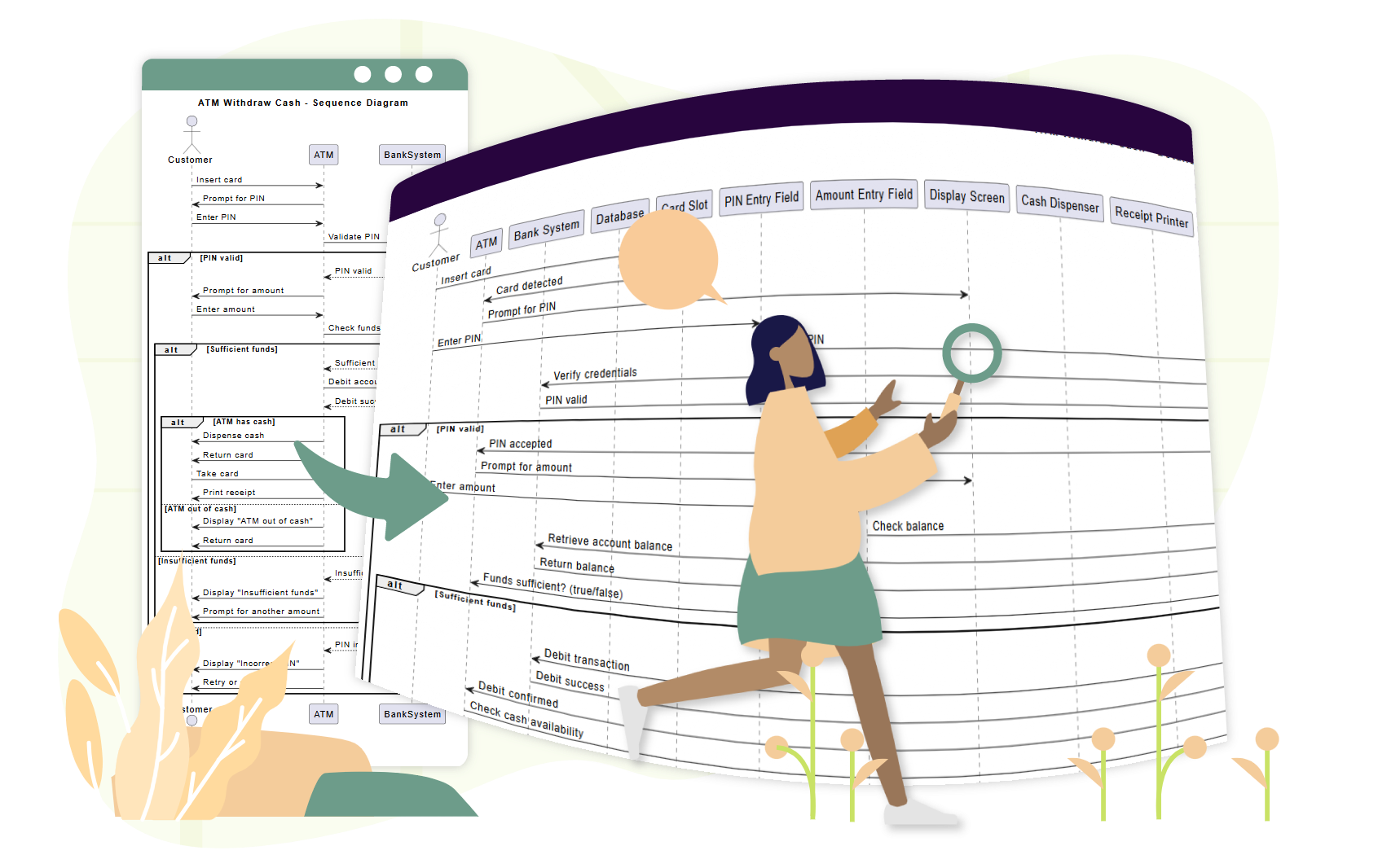
3. Sequence Diagrams (Interaction)
As a type of interaction diagram, the Sequence Diagram illustrates the dynamic behavior of a specific scenario. It details how participants (objects) exchange messages over time.
- Lifelines: Vertical dashed lines that represent a participant’s existence during the interaction.
- Activation Bars: Rectangular boxes on lifelines indicating when a participant is active or processing.
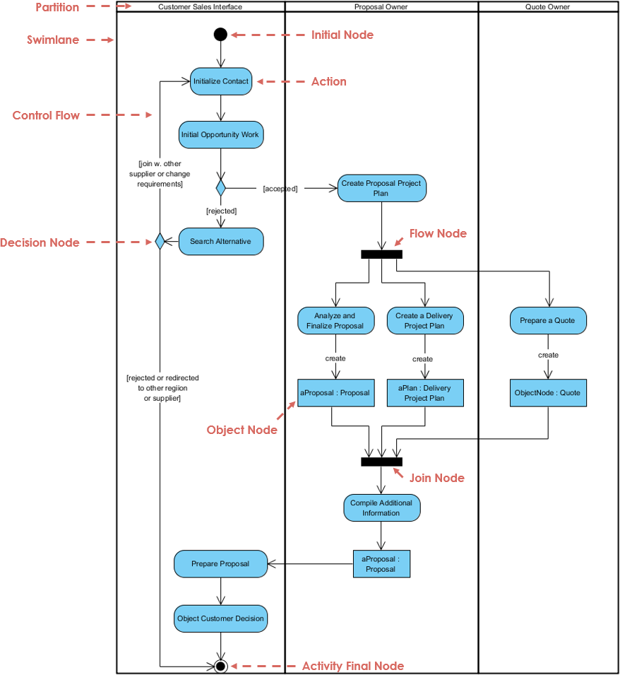
4. Activity Diagrams (Behavioral)
These activity diagrams are used to model procedural logic, complex workflows, and parallel processes.
- Forks and Joins: Visual elements used to document parallel activities that may occur in any order.
- Partitions (Swimlanes): These organize activities based on who is responsible for performing them, adding clarity to cross-functional processes.
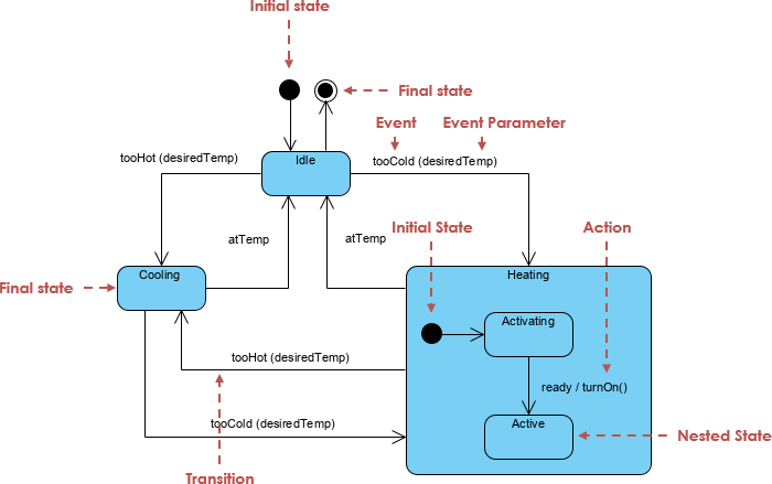
5. State Machine Diagrams (Behavioral)
State Machine diagrams illustrate the lifecycle of an object. They depict the various states an object can occupy and the events that trigger transitions between these states. These are particularly valuable for modeling objects with complex life histories, such as telephone connections or insurance claims.
Practical Modeling Guidelines
To effectively utilize UML without becoming bogged down in documentation, follow these practical guidelines:
- Agile Modeling: Prioritize modeling to understand the problem rather than merely to document it. Sketches on whiteboards captured via digital photos are often sufficient.
- The Law of Parsimony: Reduce diagrams to their essence. Typically, 20% of UML notation allows you to perform 80% of the necessary modeling work.
- Selective Selectivity: Avoid drawing diagrams for the entire system. Concentrate efforts on the most critical or difficult design areas.
- Parallel Modeling: Beginners are encouraged to switch between views, drawing dynamic interaction diagrams and static class diagrams concurrently to verify consistency.
Accelerating UML Modeling with Visual Paradigm and Generative AI
Visual Paradigm’s all-in-one platform serves as a comprehensive, professional-grade tool that directly supports the UML modeling process described above, while its newly released Generative AI features (introduced in recent versions, such as enhancements in 17.x releases around 2025–2026) accelerate and enhance every stage—from initial sketching to detailed blueprinting and even executable modeling.
Streamlining UML as Sketch, Blueprint, and Programming Language
Visual Paradigm fully supports all 13 UML 2.x diagram types, including the five essential ones for beginners: Use Case, Class, Sequence, Activity, and State Machine diagrams. Its intuitive drag-and-drop interface, extensive shape libraries, and automatic layout tools make it ideal for quick whiteboarding-style sketches (UML as Sketch), while robust features like code generation/reverse engineering, model consistency checks, and version history enable precise forward/reverse engineering (UML as Blueprint). For advanced users pursuing UML as a Programming Language, the platform offers model-to-code transformation across languages like Java, C++, and more, producing executable specifications with minimal manual coding.

The platform’s collaborative workspace (via Visual Paradigm Online/Cloud) allows teams to co-edit diagrams in real time, add annotations, track changes, and capture whiteboard photos or quick sketches—perfectly aligning with Agile Modeling principles, where the focus is on understanding rather than exhaustive documentation.
How AI Support Revolutionizes the Modeling Process
Visual Paradigm’s integrated Generative AI (including an AI Chatbot accessible in both desktop and online editions, plus specialized AI Diagram Generators and refinement tools) supercharges productivity by handling tedious tasks and providing intelligent assistance, letting modelers concentrate on high-value object-oriented thinking and responsibility assignment.
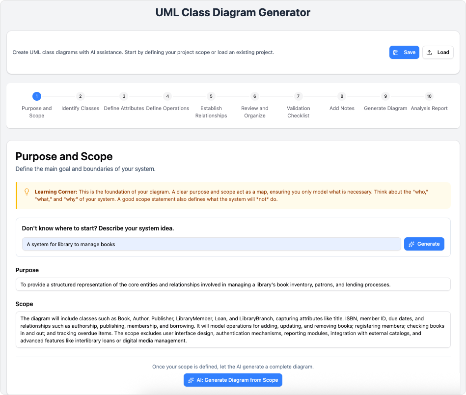
- Rapid Diagram Generation from Text (Text-to-Diagram): Describe a system scenario, use case, or problem in natural language (e.g., “Create a class diagram for a banking system with accounts, transactions, and customers, including inheritance for savings and checking accounts”), and the AI instantly generates compliant UML diagrams—such as Class, Use Case, Sequence, Object, or even Timing diagrams. This accelerates UML as Sketch for exploring ideas and jumps straight into detailed views, reducing the blank-canvas friction emphasized in practical guidelines.
- AI-Powered Refinement and Analysis: For existing diagrams, use tools like the AI Sequence Diagram Refinement Tool, AI Use Case Diagram Refinement Tool, or general AI critique features. The AI suggests improvements for better maintainability, validates relationships (e.g., distinguishing composition vs. aggregation), analyzes design quality, and provides reports or educational notes on OO principles—directly supporting the core skill of thinking in objects and responsibility-driven design.
- Specialized AI Generators for Beginners: Features like AI Use Case Description Generator, AI Problem Description Generator, AI Textual Analysis, and AI-Powered Use Case Scenario Analyzer help beginners translate requirements into structured use cases, identify actors/system boundaries, and factor in includes/extends—making the graphical “table of contents” easier to build accurately.
- Parallel and Selective Modeling Support: Switch seamlessly between diagram types (e.g., generate a Sequence Diagram from a Class Diagram context or vice versa) while the AI ensures consistency across views. Focus effort on critical areas by generating only what’s needed, adhering to the Law of Parsimony and Selective Selectivity.
- Educational and Collaborative Boost: The AI Chatbot acts as an on-demand tutor—explaining concepts (e.g., “difference between generalization and association”), generating examples, or suggesting parallel dynamic/static views for verification. Teams benefit from synchronized workspaces, where AI-generated elements can be refined collaboratively.
By combining robust UML tooling with these AI capabilities, Visual Paradigm empowers beginners to quickly move beyond notation mastery toward excellent OO designs, while experienced modelers achieve faster iteration, higher-quality outputs, and reduced documentation overhead—fully embracing agile, parsimonious, and focused modeling practices. Whether you’re sketching on a digital whiteboard, building detailed blueprints, or generating executable models, the platform’s AI turns complex UML workflows into efficient, intelligent processes.