Introduction to Use Case Diagrams
Use case diagrams are among the most accessible and vital components of the Unified Modeling Language (UML). Unlike other diagrams that detail the technical implementation or logic flow, a use case diagram focuses strictly on what the system does from the user’s perspective. It maps out the functional requirements, visualizing the interactions between the system and external entities.
This guide covers key concepts, standard notation, relationships, and provides actionable steps to create these diagrams using Visual Paradigm, highlighting both traditional manual methods and modern AI-powered tools.
What is a Use Case Diagram?
A use case diagram provides a high-level view of a system’s scope and boundaries. It visualizes thre distinct elements:
- Actors: The users, roles, or external systems that interact with the application.
- Use Cases: The specific goals or functionalities the system provides to the actors.
- Relationships: The lines connecting actors to use cases, or use cases to one another.
Primary Purpose
These diagrams serve several critical roles in the software development lifecycle (SDLC):
- Scope Definition: They clearly define what is inside the system boundaries and what is external.
- Requirement Capture: They communicate functional requirements early in the project.
- Stakeholder Communication: Because the notation is simple, non-technical stakeholders (such as business managers) can easily understand and validate the requirements.
- Foundation for Testing: They act as a blueprint for creating user stories, detailed test cases, and ensuring traceability.
Key Concepts and UML Notation
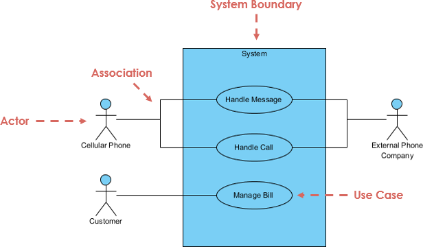
To create a standard-compliant diagram, it is essential to understand the specific symbols used in UML.
| Element | Symbol / Description | Naming Convention |
|---|---|---|
| Actor | Represented by a stick figure or a rectangle with the «actor» stereotype. It represents an external entity (human, device, or system) interacting with the system. | Noun (e.g., Customer, Admin, Payment Gateway) |
| Use Case | An oval (ellipse) containing the name of the functionality. It represents a single, cohesive goal. | Verb + Noun (e.g., Place Order, Login) |
| Association | A solid line connecting an actor to a use case. It indicates participation or initiation. | — |
| System Boundary | A rectangle enclosing the use cases. Actors are placed outside this boundary. | System Name (e.g., Banking System) |
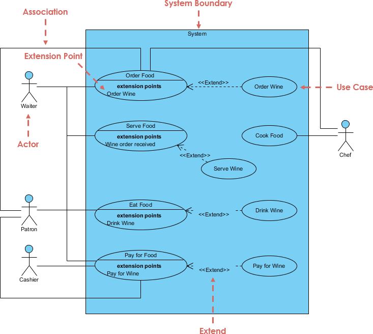
| <<include>> | A dotted arrow pointing from a base use case to an included use case. This signifies mandatory reuse (the base case always runs the included steps). | Used for factoring out common behavior. |
| <<extend>> | A dotted arrow pointing from an extending use case back to the base use case. This signifies optional or conditional behavior. | Used for error handling or optional features. |
Tips for Relationships
- Use <<include>> when a step is required across multiple use cases (e.g., “Authenticate User” is needed for both “Withdraw Cash” and “Transfer Funds”).
- Use <<extend>> for variations that only happen under specific criteria (e.g., “Apply Discount” only occurs if the user has a coupon code during “Checkout”).
How to Create a Use Case Diagram in Visual Paradigm
Visual Paradigm offers professional modeling capabilities ranging from precise desktop controls to rapid AI generation.
Option 1: Manual Creation (Desktop or Online)
For full control over layout and specifics, follow these steps:
- Initialize Project: Open Visual Paradigm and navigate to File > New Project.
- Create Diagram: Go to Diagram > New, select Use Case Diagram, and name it (e.g., “E-Commerce Use Case Diagram”).
- Define the Boundary: From the toolbar, select the System tool and draw a rectangle on the canvas. Name it (e.g., “QuickCart E-Commerce”).
- Add Actors and Use Cases:
- Click Actor and place it outside the boundary. Name it (e.g., “Customer”).
- Click Use Case and place it inside the boundary. Name it (e.g., “Browse Products”).
- Draw Relationships: Use the Association tool (solid line) to connect actors to use cases. For advanced logic, use the Resource Catalog to drag <<include>> or <<extend>> relationships between use cases.
- Document: Right-click any use case and select Open Specification to add detailed descriptions or flows of events.
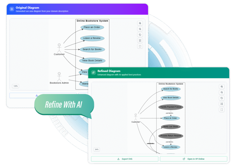
Option 2: AI-Powered Generation (Use Case Modeling Studio)
For rapid prototyping, Visual Paradigm’s AI tools can generate comprehensive diagrams from simple text prompts.
- Navigate to the Visual Paradigm AI-Powered Use Case Modeling Studio.
- Input a description of your system.
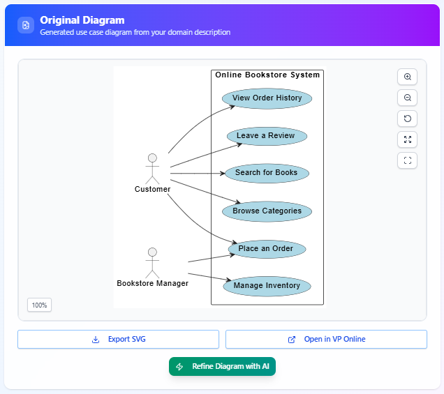
Example Prompt: “An online bookstore where customers browse/search books, add to cart, and checkout. Admins manage inventory.” - The AI will automatically generate:
- A list of identified actors and use cases.
- Detailed textual descriptions including preconditions and basic flows.
- A complete Use Case Diagram with intelligent placement of associations, includes, and extends.
- Review the preview, refine the prompt if necessary, and export the diagram as an SVG or open it in the editor for further refinement.
Real-World Examples
To better understand how to structure these diagrams, consider the following industry-standard scenarios.
1. ATM Banking System
This is a classic example often used to demonstrate include and extend relationships.
- Actors: Customer, Bank System.
- Use Cases: Withdraw Cash, Check Balance, Change PIN, Transfer Funds.
- Key Relationships:
- Withdraw Cash <<include>> Authenticate User (Mandatory security step).
- Transfer Funds <<extend>> Check Balance (Optional check if funds are low).
2. Online Shopping (E-Commerce)
A more complex system involving multiple user roles.
- Actors: Guest Customer, Registered Customer, Administrator, Payment Gateway.
- Use Cases: Search Products, Add to Cart, Place Order, Manage Catalog (Admin).
- Key Relationships:
- Checkout <<include>> Process Payment.
- Apply Coupon <<extend>> Checkout (Only occurs if the user has a code).
3. Library Management System
- Actors: Member, Librarian.
- Use Cases: Borrow Book, Return Book, Reserve Book, Search Catalog.
- Key Relationships:
- Borrow Book <<include>> Search Catalog (User must find the book first).
- Renew Loan <<extend>> Borrow Book.
Best Practices and Common Pitfalls
Creating effective UML diagrams requires balancing detail with clarity.
Best Practices
- Keep it Simple: An ideal diagram has 5–15 use cases. If the system is complex, split it into multiple diagrams or use packages.
- User-Centric Naming: Always name use cases as Verb + Noun phrases that reflect user goals (e.g., “Generate Report”), not system processes.
- Always Use Boundaries: Clearly define what is inside the system versus what is external using the System Boundary rectangle.
- Add Specifications: A diagram is only a map. Use Visual Paradigm’s flow-of-events editor to write the underlying logic, preconditions, and post-conditions.
Common Mistakes to Avoid
- Missing System Boundary: Failing to draw the box around use cases makes the scope ambiguous.
- Diagramming Process Flow: Do not try to show the sequence of steps (e.g., step 1, step 2) inside a use case diagram. Use an Activity Diagram or Sequence Diagram for that purpose.
- Confusing Include vs. Extend: Remember: Include is mandatory; Extend is optional.
- Noun-Only Names: Avoid naming use cases “Order” or “Login Page.” Use “Place Order” or “Login to System.”
Why Choose Visual Paradigm?
Visual Paradigm stands out as a preferred tool for UML modeling due to its seamless blend of traditional features and modern innovation. It offers intuitive drag-and-drop interfaces with smart connectors that auto-route for clean layouts. The AI acceleration features allow teams to move from a rough idea to a fully documented diagram in seconds.
Furthermore, it supports robust collaboration through cloud sharing, versioning, and the ability to link use cases to other project artifacts like traceability matrices and user stories. Whether you are using the free online edition or the comprehensive desktop suite, Visual Paradigm ensures your use case diagrams are not just drawings, but functional blueprints for development.