


In the realm of software engineering and Object-Oriented Design (OOD), the UML Class Diagram serves as the backbone of system modeling. It is a static structure diagram that describes the architecture of a system by displaying its classes, their attributes, operations (methods), and the intricate relationships among objects. Whether you are formulating a domain model or detailing software specifications, understanding class diagrams is essential for translating conceptual blueprints into functional code.

Understanding the Anatomy of a Class
At the heart of the diagram is the Class, which acts as a blueprint for objects. While objects are usable instances that contain data and behavior, the class defines the rules for those objects. In UML notation, a class is represented by a rectangle divided into three specific partitions:
- Class Name: Located in the first (top) partition. This is mandatory. Abstract classes are typically written in italics.
- Attributes: Located in the second partition. These represent the state or structural features of the class (member variables).
- Operations (Methods): Located in the third partition. These define the behavioral features or services the class provides.
Visibility and Access Control
To define encapsulation, UML uses specific symbols before attribute and operation names to denote visibility. This dictates which other classes can access these members.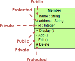
| Symbol | Visibility Type | Description |
|---|---|---|
| + | Public | Accessible by any other class. |
| – | Private | Accessible only within the class itself. |
| # | Protected | Accessible by the class and its subclasses (derived classes). |
| ~ | Package | Accessible by any class within the same package. |
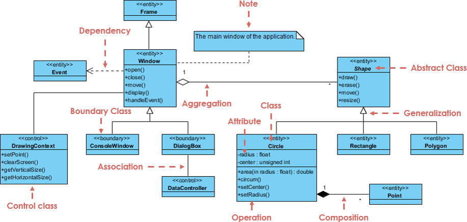
Deciphering Class Relationships
The power of a UML class diagram lies in how it depicts the interaction between classes. Just as code implementation relies on logic, UML relies on specific connectors to convey intent. Below are the primary relationship types: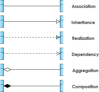
1. Inheritance (Generalization)
Inheritance represents an “IS-A” relationship. It is a taxonomic relationship where a specific classifier (child) inherits features from a general classifier (parent). For example, a Circle is a Shape.
- Notation: A solid line with a hollow arrowhead pointing from the child class to the parent class.
- Usage: Used to simplify analysis models by introducing commonality in a superclass.
2. Association
This is a structural link between peer classes, often described by a verb (e.g., “Teacher teaches Student”). It signifies that two classes are related but creates a loose coupling.
- Notation: A solid line connecting two classes.
- Multiplicity: Indicates how many objects participate (e.g.,
1,0..1,1..*).
3. Aggregation
Aggregation is a special form of association representing a “PART-OF” relationship. However, it implies a weak ownership. The part can exist independently of the whole. For instance, a Car has Tires, but if the Car is destroyed, the Tires can still exist.
- Notation: A solid line with an unfilled (hollow) diamond at the end connected to the aggregate (parent) class.
4. Composition
Composition is a stricter form of aggregation. It represents a strong ownership where the part cannot exist without the whole. If the parent object is destroyed, the child objects are also destroyed. An example is a House and its Rooms.
- Notation: A solid line with a filled (solid) diamond at the end connected to the composite (parent) class.
5. Dependency
This represents a “uses” relationship. It exists when one class interacts with another specifically as a parameter in a method or a local variable, rather than as a field. Changes to the definition of the supplier class may affect the client class.
- Notation: A dashed line with an open arrow pointing to the dependency.
Guidelines for Effective Class Diagrams
Creating a readable and accurate diagram requires adherence to specific guidelines.
- Use Standard Naming Conventions: Class names should be nouns (e.g., Customer, Order), generally capitalized. Association names should be verbs (e.g., places, contains).
- Identify the Perspective: Before drawing, decide if you are modeling a Conceptual view (domain concepts), a Specification view (interfaces), or an Implementation view (code-specific).
- Manage Complexity: Do not attempt to model the entire system in a single diagram. Divide the system into multiple diagrams, focusing on specific modules or business areas.
- Label Multiplicity Explicitly: Always clarify if a relationship is one-to-one, one-to-many, or many-to-many to ensure the database or code logic reflects the business requirement.
Real-World Example: Order Processing System
Consider a standard e-commerce scenario involving a Customer, an Order, and a Product. Here is how the relationships translate into a Class Diagram structure:
- Customer and Order (Association): A Customer places an Order. The multiplicity is
1Customer to0..*Orders. - Order and LineItem (Composition): An Order is composed of LineItems. If the Order is deleted, the LineItems lose their meaning and are destroyed. This is a filled diamond pointing to Order.
- LineItem and Product (Association/Aggregation): A LineItem refers to a Product. However, the Product exists independently of the LineItem (it stays in the inventory). This is a standard association or weak aggregation.
- Payment (Realization): An interface named IPayment might be realized by classes CreditCardPayment and PayPalPayment.
Tips and Tricks for Optimization
Apply these tips to elevate your diagrams from simple drawings to professional technical artifacts:
- The “Read Aloud” Test: Read your relationships out loud. “A Car consists of Wheels.” If it sounds awkward, check if you are using the correct arrow direction or relationship type.
- Parameter Directionality: In the operations partition, you can specify parameter direction using
in,out, orinoutbefore the parameter name to clarify data flow. - Abstract Italics: If a class cannot be instantiated directly (it is abstract), ensure its name is italicized. This is a subtle but critical signal to developers.
- Avoid Crossing Lines: While modern tools like Visual Paradigm handle routing well, try to manually arrange classes to minimize crossing lines, which improves readability significantly.
Class Diagram Audit Checklist
Before finalizing your UML Class Diagram, run it through this actionable checklist:
- [ ] Completeness: Are all necessary classes for the specific module present?
- [ ] Visibility: Are attributes and operations marked with correct visibility symbols (+, -, #)?
- [ ] Relationship Accuracy: Have you correctly distinguished between Aggregation (hollow diamond) and Composition (filled diamond)?
- [ ] Multiplicity: Is cardinality defined on both ends of associations (e.g., 1..*)?
- [ ] Navigability: Do arrows clearly indicate which class can access the other?
- [ ] Naming: Are class names nouns and unique? Are relationship verbs clear?
- [ ] Generalization: Does the inheritance hierarchy make sense (Is-A relationship)?